WeChat Official Account: Chip Home (ID: chiphome-dy)
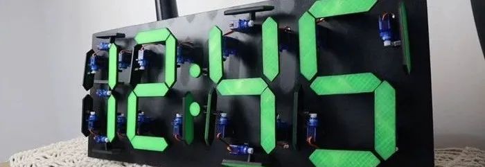
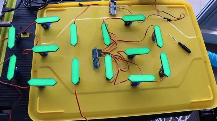
Today, I share a creative electronic DIY project, using a 16-channel PCA9685 driver module and a DS1302 real-time clock module to build a mechanical seven-segment display clock, powered by 28 servos and controlled by an Arduino Uno.
-
Arduino Uno -
DS1302 Clock Module -
2 x PCA9685 16-channel Servo Driver Modules -
28 x 9g Servos -
Dupont Wires -
Male Header Pins -
Female Header Pins -
3mm MDF -
Black Spray Paint -
5V 5A Battery -
12V Power Supply
You will also need to 3D print some components. If you don’t have a 3D printer and enjoy making things, you should definitely consider getting one. If you don’t want to buy one, you can also have them printed online.
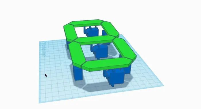
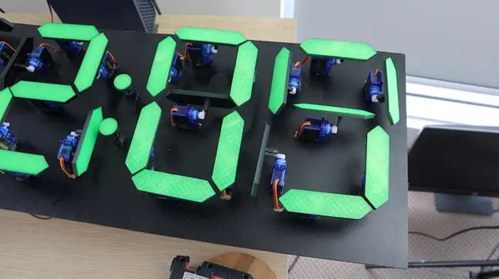
First, a separate seven-segment display digit was designed, which can be activated by the servos for each segment. The servos move each segment vertically when turned on, and move 90 degrees to the side when turned off.
These segments are designed to be directly glued onto standard servo arms, so no additional hardware is needed.
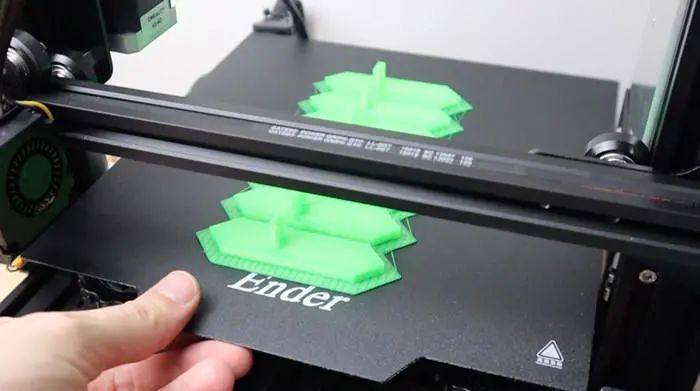
The 3D printing files can be obtained at the end of this document.
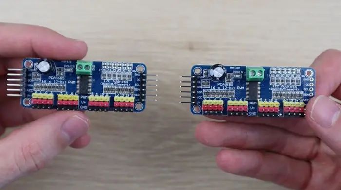
Two PCA9685 16-channel PWM drivers were used, which allow you to control up to 16 servos on each board and link up to 62 boards together via I2C, which only uses two IO pins on the Arduino. This means, theoretically, you can control up to 992 servos independently with just two IO pins. We will use one for the two-hour digits and one for the two-minute digits.
To link the two, you need to first add a pin header to the other side of the first board and then change the address on the second board for unique identification.
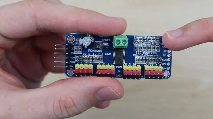
This is achieved via the small terminal above the bridge board. They work like dip switches, allowing you to set different addresses for each board. You only need to bridge a set of terminals on the far right of this project.
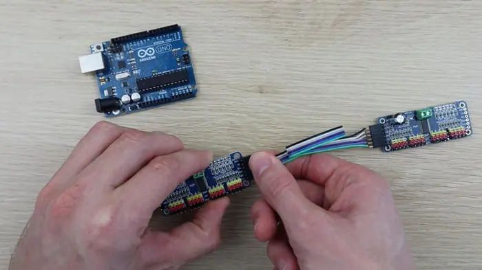
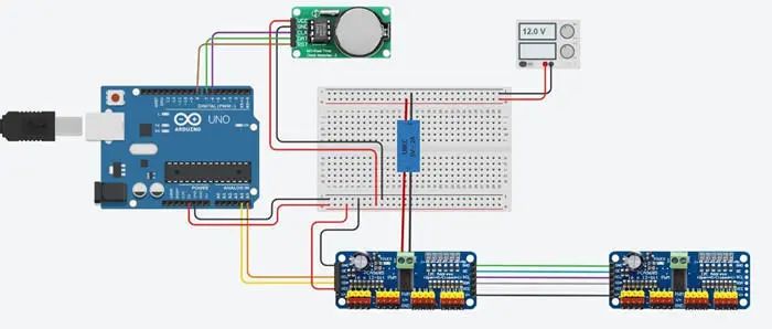
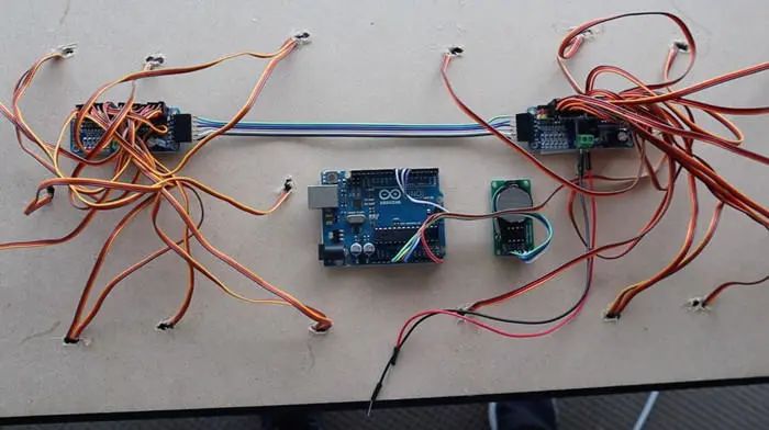
After changing the address, make a connection wire to link the two modules together, then connect the clock module and Arduino Uno, as shown in the circuit diagram below:
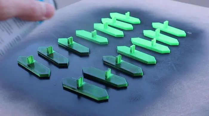
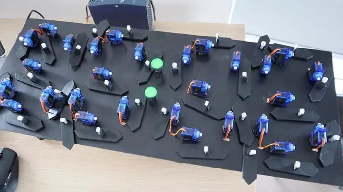
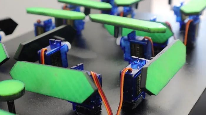
After completing the 3D printed segments, you need to spray paint the back and sides of the segments black to match the background, making them invisible when turned on. If they are left green, when the segments rotate 90 degrees, they will still land along the visible line. Spray paint the back and sides of the segments so they are not visible from the side.
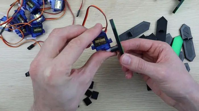
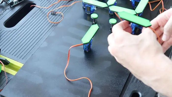
Next, use hot glue to attach the segments to the servo arms. The simplest way is to place the arm on the servo and glue the segment to the servo and arm assembly, which also allows you to check if it is attached directly.
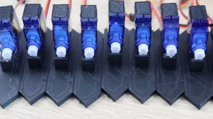
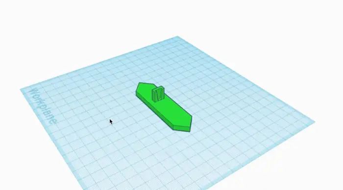
You will also need to glue small 3D printed spacers to the bottom of each servo, which help the servos stand upright when glued to the backplate.
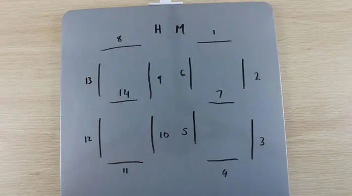
Number each segment to track them in the code. This numbering is repeated on the hour and minute boards.
Before gluing the digits to the backplate, test them on a flat surface. This way, they can move without the risk of moving in the wrong direction or moving too far and colliding with each other, which could damage the segments or cause the gears on the servos to slip off.
Once you are satisfied with the movement of the digits, you can proceed to the next step.
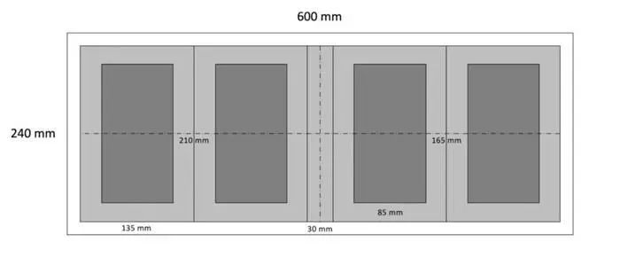
A backplate at least 600mm x 240mm is needed. The light gray large box is the area where the segments will move when rotated; they must be at least 210mm x 135mm so adjacent segments do not touch when they all move out to the closed position. The darker internal rectangle is the centerline of the six servos that make up the outside of each digit. Finally, leave 30mm between the inner digits.
After measuring, cut the backplate from a piece of 3mm MDF and spray it black.
Mark the positions of the segments on the backplate according to the diagram, and then begin gluing them in place.
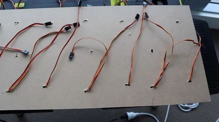
Once the digits are completed, you need to hide the wiring. Drill holes in the back of the board near each servo so the servo wires can pass through, and number the leads in advance. Apply a small drop of glue on each to secure them in place.
Use double-sided tape to attach the four electronic boards to the back of the clock. You can also install them with screws, just make sure the screws do not go all the way through the MDF to the other side.
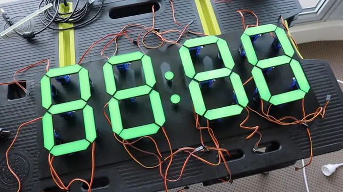
Before downloading the final version of the software, remove the mechanical arms from the servos to make fine adjustments to the standing position without worrying about them colliding with each other. A good idea is to remove the arms from the servos and keep them off until you power up the boards and set all the servos to the “on” position (showing 88:88). This way, you can put them back in place without worrying about them colliding and crashing into each other.
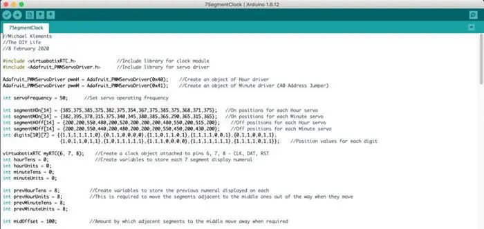
The program uses a clock driver library and a servo driver library; all the code can be obtained by replying Mechanical Clock in the official account backend.

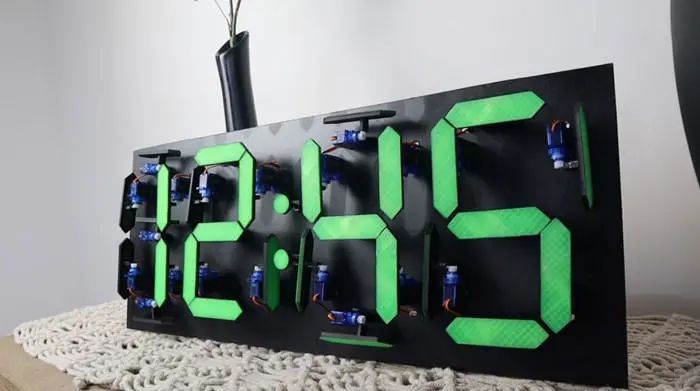
You can now use your mechanical seven-segment display clock.
Attached is a detailed video tutorial; the video is quite long, so it is recommended to watch it in a WiFi environment.
Original Article Link: https://www.instructables.com/id/Mechanical-Seven-Segment-Display-Clock/
Disclaimer:Copyright belongs to the original author. If there are any copyright issues, please contact me for removal. Thanks again to the official account TonyCode for the translation and organization.
Previous Excellent Articles Collection