Five years ago, a new adjustable ECU/ECM claimed to be “unhackable” and dominated the market at that time; it was the GM E41 ECM Services (L5P). This ECU/ECM first appeared on the L5 Peter Max truck in 2017, and many believed that such ECUs/ECMs could not be hacked or tuned.
As experts from the external network gradually dissected and analyzed it, its defenses began to crumble. Since this product’s defenses were breached, HSM (Hardware Security Module) has gradually been integrated into vehicles, leading to a much more reliable and secure automotive landscape today.
So, how was this ECU breached? What does the entire ECM look like when disassembled, and what points are worth noting inside? What insights does this provide for our current automotive development? Let’s revisit these events.
Removing the Shell: A Look at the Overall Structure
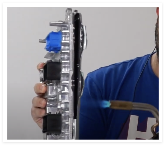
To conduct an in-depth study, I purchased an E-40 ECU (T1 model), which is used for certain rail models. The shell of this ECU is completely sealed, and I had to use a screwdriver to pry open the curled edges and heat it with a torch to soften the adhesive, ultimately succeeding in opening the shell.
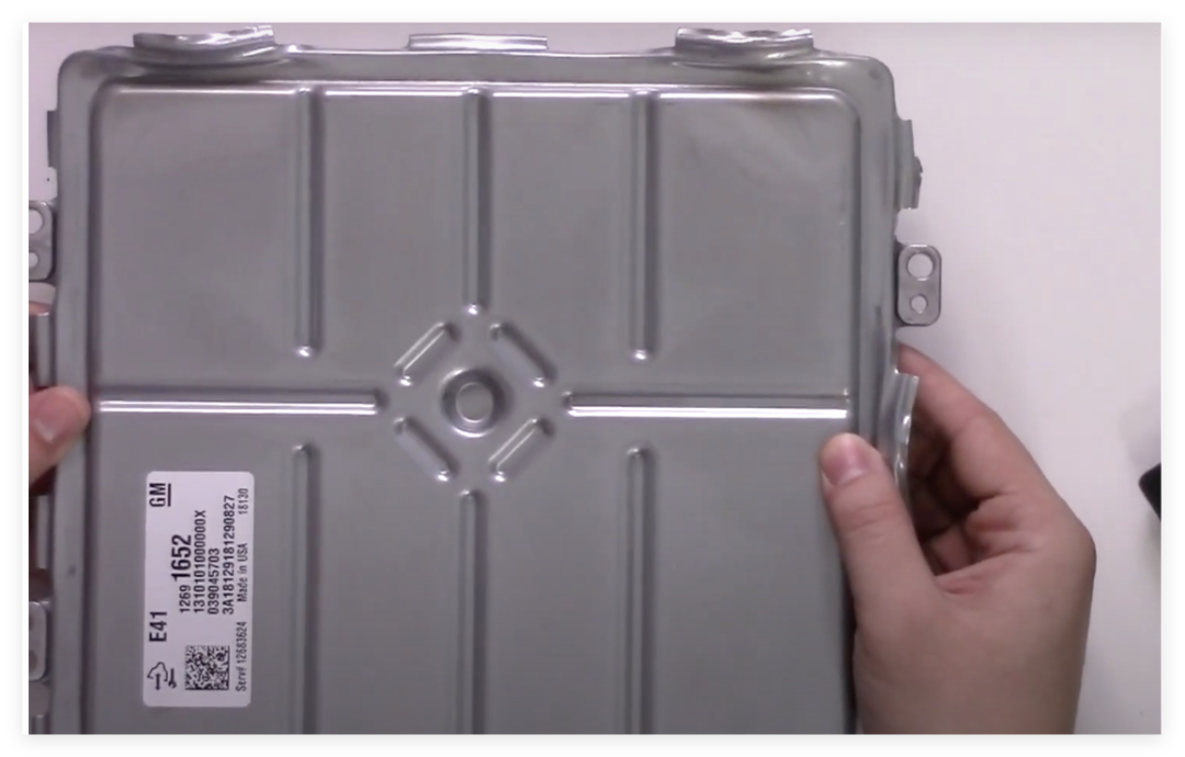
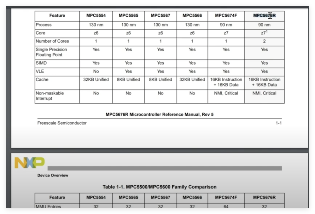
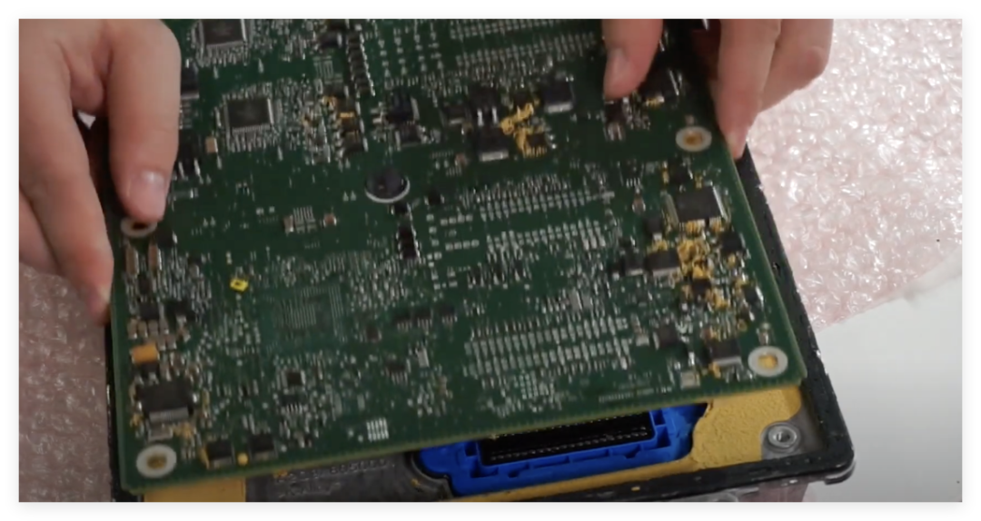
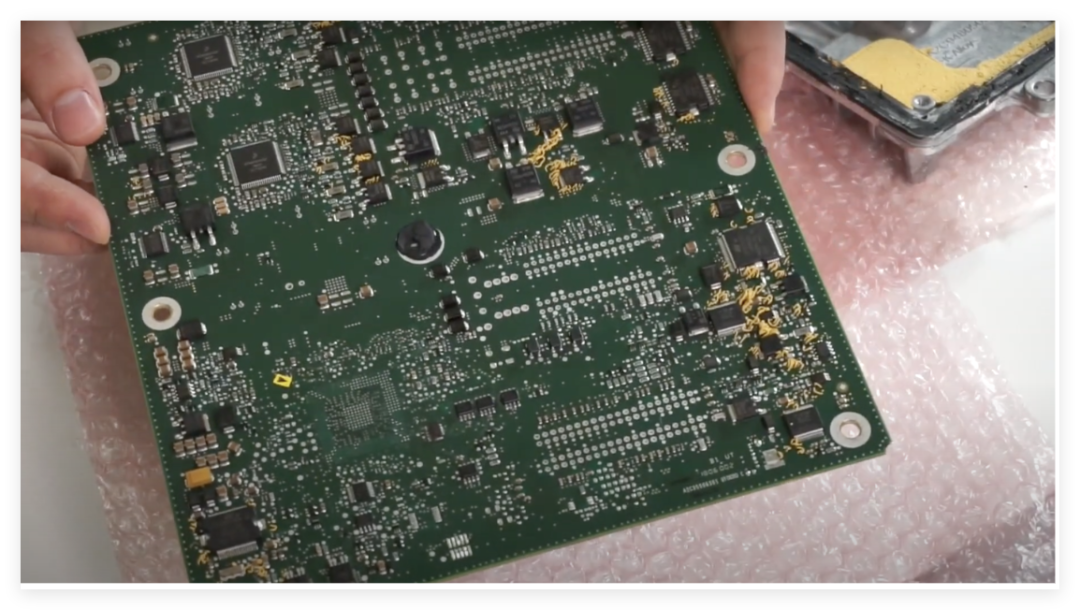
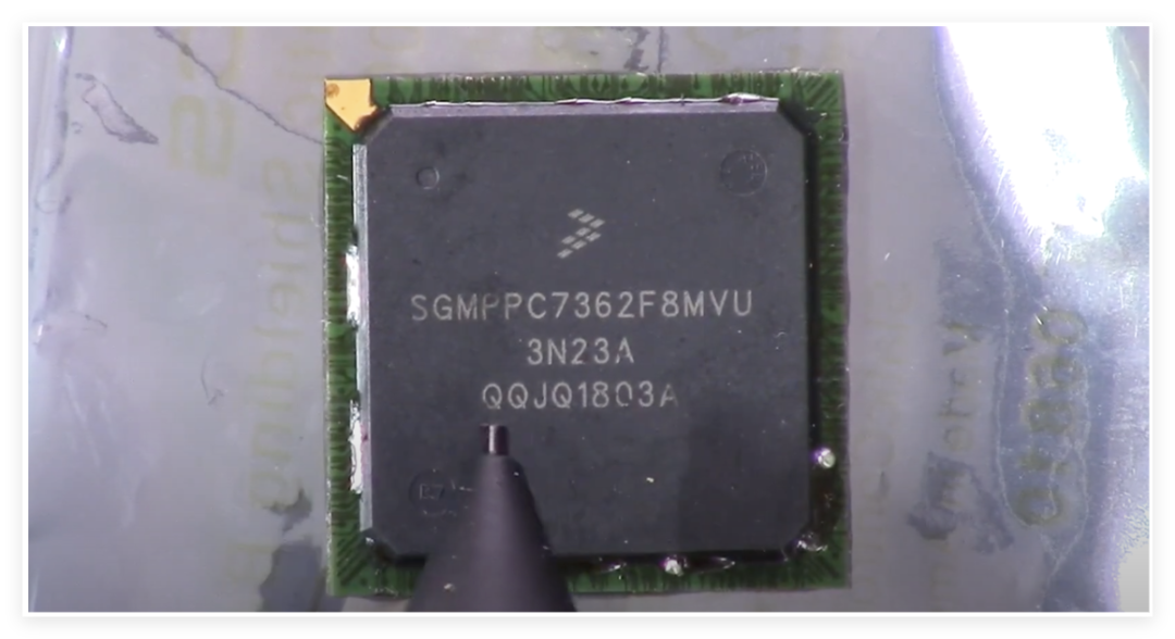
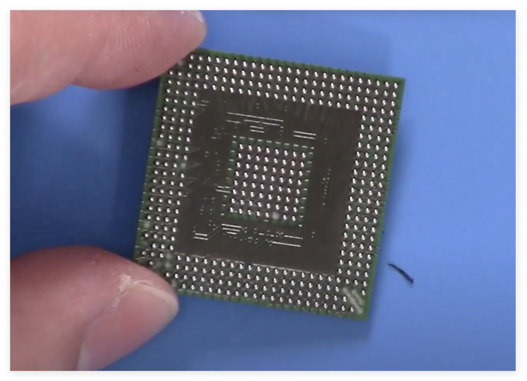
Upon opening, I found that the PCB was covered with a material similar to potting compound, possibly for heat dissipation or moisture protection. In one corner of the mainboard, there is a BGA-packaged main control chip, surrounded by various driver chips used to control ignition coils, fuel injection, etc. Notably, this ECU does not use traditional moisture-proof coatings but relies entirely on the shell sealing for moisture protection, making circuit detection easier.Upon microscopic examination, the model of the main control chip is not common, but after searching, it appears to be the Freescale (now NXP) MPC5676R, a dual-core processor based on the PowerPC architecture. After reviewing the datasheet, I noted that this chip does not have a hardware security module (HSM), which means its security may rely on software-level protective measures. In contrast, higher-end ECUs (like the E99 model) may have upgraded to chips with HSM.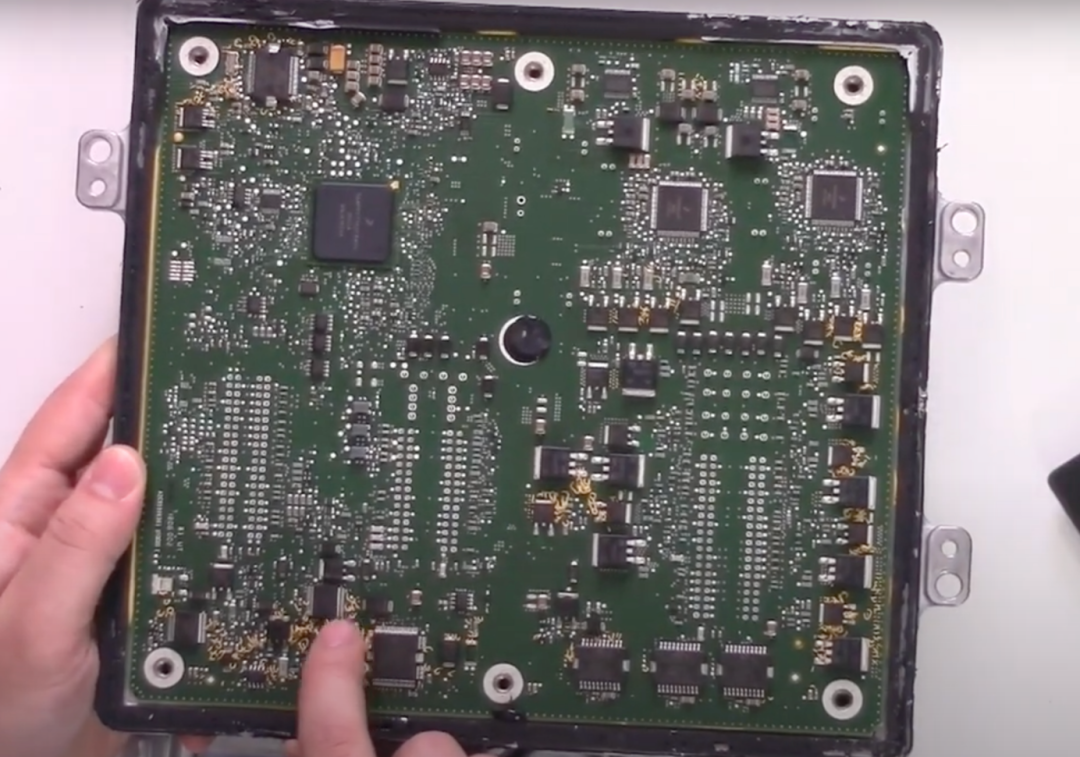
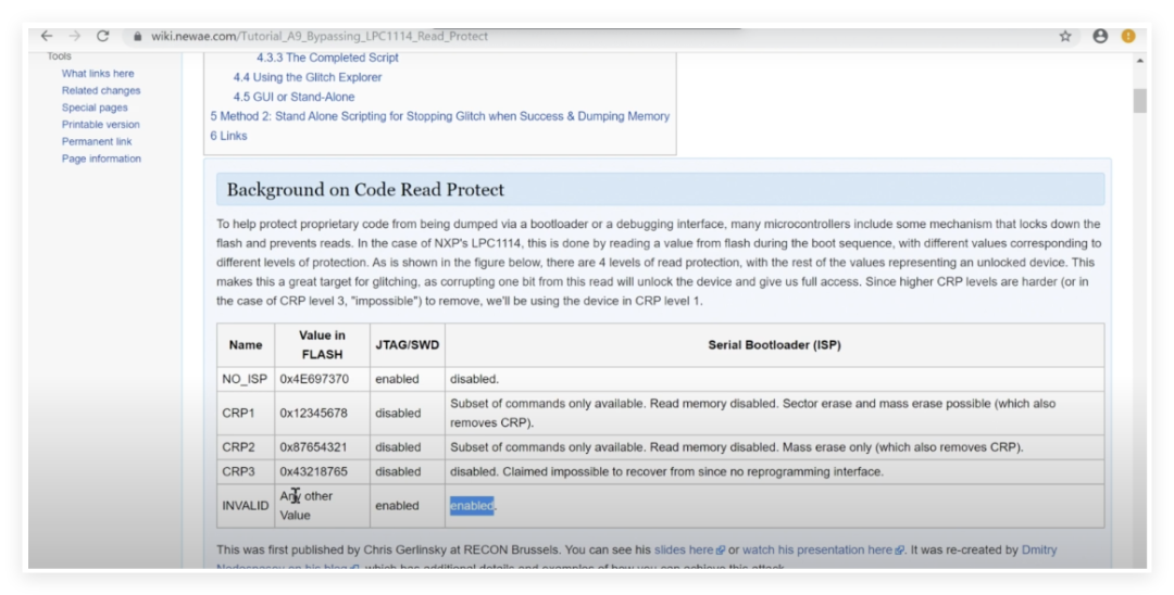
In one corner of the PCB, I found a pin that appears to be a debugging interface, but it is likely disabled. According to the datasheet, the JTAG debugging function of this chip can be enabled or disabled via a “censorship control word” (a configuration word stored in flash memory). If this value is compromised, the chip enters a “censored” state, disabling the debugging interface and flash read functions.

Interestingly, the chip also supports a serial bootloader and can enter this mode through specific pin configurations. If physical access to these pins is possible, it may be possible to exploit public passwords to bypass some security restrictions. However, since the ECU’s pins are crimped onto the PCB, directly probing these pins is quite difficult.
Follow and star the non-network eeFocus
Scan the code and reply “trial” to join the board trial group and participate in activities

According to Riscure’s research paper “Safety ≠ Security”, certain automotive ECUs’ JTAG interfaces can be re-enabled through fault injection. The paper mentions that even with a low success rate (e.g., 0.3%), a single successful attack may still bypass password protection. Therefore, I plan to further attempt to interfere with the chip’s configuration word through physical means (such as heating or voltage spikes) to explore whether it is possible to enable the debugging interface or access flash data.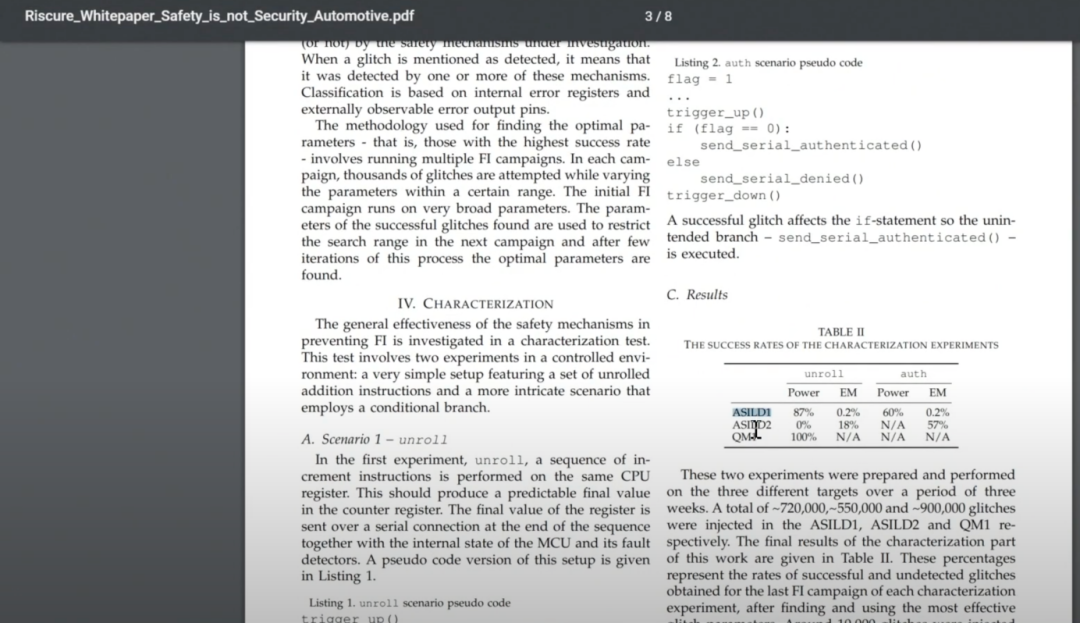 This ECU represents a design trend in modern automotive electronic systems: enhancing security through a combination of hardware sealing and software protection. However, with the advancement of reverse engineering techniques, even “unhackable” ECUs may have vulnerabilities. In the future, I hope to further study higher-end ECU models (like the E99) and explore the implementation of their hardware security modules.Through disassembly, we can see the complexity of modern automotive electronic security and realize that the technical game between manufacturers and hackers continues. For the automotive industry, achieving a balance between convenience and security will be a long-term challenge.
In-Depth Exploration of the Main Control and Debugging Interface
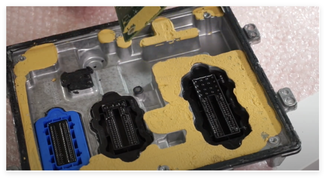
In the previous section, I successfully disassembled the ECU’s shell, but the mainboard was still firmly fixed inside. After some effort, I finally removed the mainboard intact by removing the crimped pins of the connectors. This section will focus on analyzing the internal structure of the mainboard, particularly the debugging interface and potential attack surfaces.The ECU’s mainboard is secured by multiple crimp-style connectors, which are not soldered but connected to the PCB through physical crimping. To separate the mainboard, I used a torch to heat the plastic of the connectors, softening it before pulling out the pins one by one. Additionally, the back of the mainboard is covered with a layer of black thermal compound for heat dissipation of the main control chip (BGA package), which also increases the difficulty of separation. 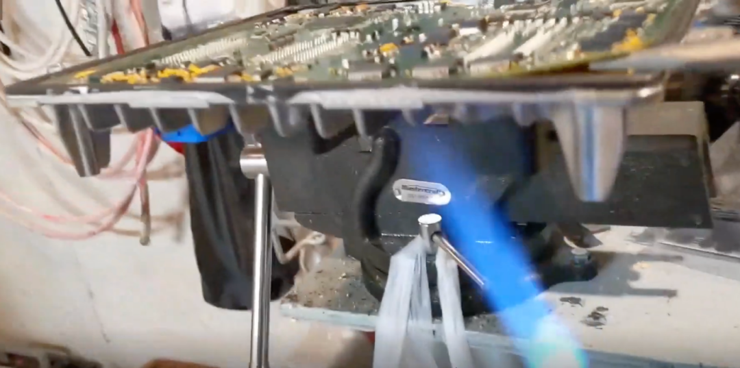
The main control chip is marked as MPC5676R, belonging to NXP (formerly Freescale) PowerPC architecture dual-core processor. By comparing the pin definitions in the datasheet and PCB traces, the authenticity of the chip was confirmed. Notably, this chip does not have a hardware security module (HSM), and its security relies on software protection mechanisms (such as flash encryption and disabling the debugging interface).
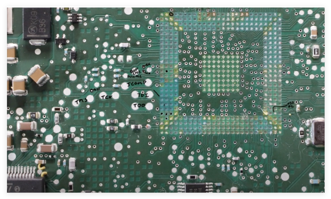
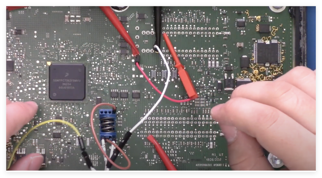
At the bottom of the PCB, I discovered a pin array that appears to be a debugging interface. Through the datasheet and trace analysis, I confirmed the following key information:
- JTAG Interface: Includes TDO, TCK, TMS, TDI, distributed at specific test points on the PCB.
- Serial Bootloader: The serial mode can be enabled via the `BOOT_CONFIG1` pin, with communication achieved through `TXDA` and `RXDA`.
-
Reset Control: The `RESET` pin and `RESET_OUT` signal can be used for fault injection or monitoring device status.
Currently, three potential attack methods have been identified:The first is through JTAG debugging: The chip’s JTAG interface may be disabled, but physical access to the test points may allow attempts to re-enable it. If the chip’s “censorship control word” (the configuration word in flash) is compromised, it may trigger the opening of the debugging interface.The second is the serial Bootloader: By shorting the `BOOT_CONFIG1` pin, it may force entry into serial boot mode. It is necessary to bypass possible password protection (such as public passwords or flash passwords).The third is fault injection: The VSS_FL pin is a dedicated ground pin for the flash memory module, interrupting its connection may lead to abnormal flash read/write, providing opportunities for fault injection. By interfering with the clock signal (external crystal) or power supply, it may trigger unexpected behavior of the chip.The next steps include four plans:1. Obtain a new ECU: The current mainboard is damaged, and I need to wait for a new device for actual debugging tests.2. Verify JTAG functionality: Attempt to access the JTAG interface using a compatible programmer to confirm its availability.3. Explore Bootloader: Communicate with the device in serial mode, analyzing its responses and potential vulnerabilities.4. Fault injection experiments: Test the effects of interference on the VSS_FL pin and clock signal.
Testing Bootloader Functionality and Security Mechanisms
In the second part, I successfully removed the PCB from the shell. However, when taking the PCB out, I encountered a problem. There was a sticky substance underneath the printed circuit board, causing significant bending of the board. This sticky substance adhered to the circuit board, and safely removing it essentially required cutting it open. This resulted in some pads and a large number of ball grid array (BGA) contacts experiencing delamination. Nevertheless, I successfully re-balled the remaining BGA on the printed circuit board.Next, we hope to use this processed BGA to perform some operations, such as booting it up and checking the boot auxiliary module on this device, which essentially functions like a serial bootloader. We want to understand how it is configured; typically, it has a default password, but it is likely to have been changed. After that, we will study how to change it and explore some potentially helpful hardware cracking techniques.
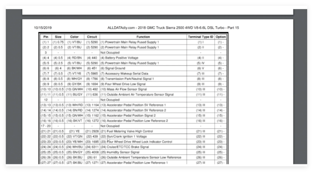
To power it, we need to refer to some materials. By checking the part number of this ECU, we can see that it is specifically used in the 2018 Chevrolet Silverado 2500 V8 6.6 model. If we look at the relevant pin output table, we find that for this large ECU connector, pin 6 is the ground pin, and pin 4 is the positive voltage pin from the battery. Other larger pins provide power to various device output fuses, and the ECU can typically turn off some sensors to save power.
Currently, the ECU requires the following pins to power on:
- Main Power (+12V): Connect to the positive terminal of the battery (confirmed according to pin definitions).
- Ignition Signal (IGN): Simulate vehicle ignition to trigger ECU startup.
-
Ground (GND): Ensure a complete circuit.
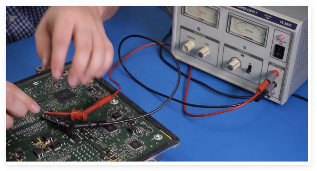
By using an external power supply and jumpers, I successfully powered on the ECU and monitored current changes, indicating that the device has entered operational status.
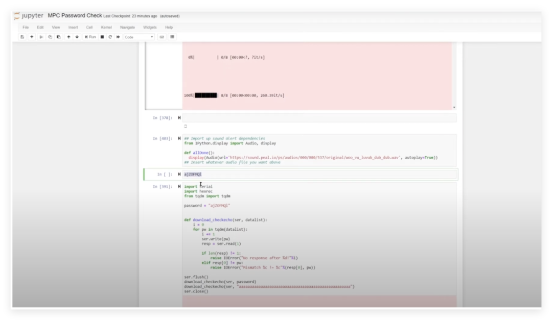
According to the chip manual, the MPC5676R supports enabling serial bootloader mode via the Boot Config pin. The steps are as follows:1. Hardware Configuration: Pull the BOOT_CONFIG1 pin high (3.3V) to force the chip into bootloader mode.Bypassing the Lin bus transceiver (by disabling its Sleep pin), directly connect to the UART interface.2. Default Password Verification: The manual states that the default password is 0xFEEDFACECAFEBEEF, but actual testing found that the ECU chip did not use the default password but instead enabled custom password protection.3. Comparative Testing: Insert a brand new chip of the same model into the development board, successfully entering the bootloader after inputting the default password, confirming that the ECU manufacturer has modified the security configuration.4. Password Protection Mechanism: The bootloader password of the ECU chip may be stored in flash memory, requiring physical means (such as fault injection or flash reading) to bypass.5. Possible Attack Directions: Attempt to interfere with the password verification process through voltage spikes or utilize the non-disabled debugging interface (such as JTAG) to extract the password.6. Hardware Verification: Set up a test environment using the development board, observing power consumption differences during password verification through **Differential Power Analysis (DPA)** to locate key operations.7. Check if VSS_FL (flash dedicated ground pin) can trigger flash read/write anomalies through interference.This experiment confirmed that the ECU manufacturer has customized protection for the bootloader, but there are still potential attack surfaces at the hardware level (such as interfaces that are not completely disabled or physical vulnerabilities).Key findings include: The bootloader password of the ECU chip is no longer the default value, requiring deeper hardware attack methods; the development board verification provides a controlled environment for research, which will be used for fault injection experiments; security protection is concentrated at the software level, while hardware design still retains debugging interfaces, which may become a breakthrough point.
Using Electromagnetic Fault Injection to Crack the ECU Bootloader Password
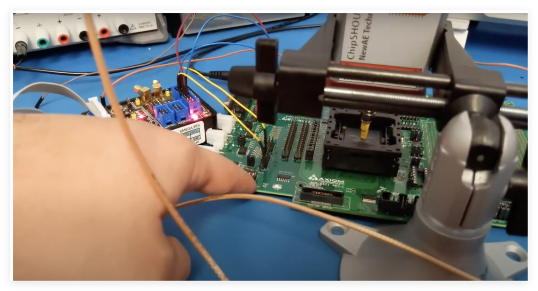
Next, I began using electromagnetic faults to crack the ECU’s password, and this time, I finally breached the ECU’s defenses.Summary: Electromagnetic Fault Injection (EMFI) is a well-known method for introducing faults in digital devices for security analysis. Such faults can be viewed as similar to those that naturally occur in digital devices, which is a known issue in designing safety-critical systems. Many standards have been established for safety-critical systems, including those that specify using particle sources to increase the natural fault occurrence rate.This time, using the MPC 5676 development board for ECU security research, we inserted the microcontroller disassembled from the ECU into the slot. The experiment employed an electromagnetic fault injection tool, ChipShooter, to implement precise interference through a 1mm probe.It is equipped with a 1mm tip that can inject faults into the target device. The device has a trigger line that supports hardware triggering. With the help of ChipShield, triggering operations are based on serial communication traffic.
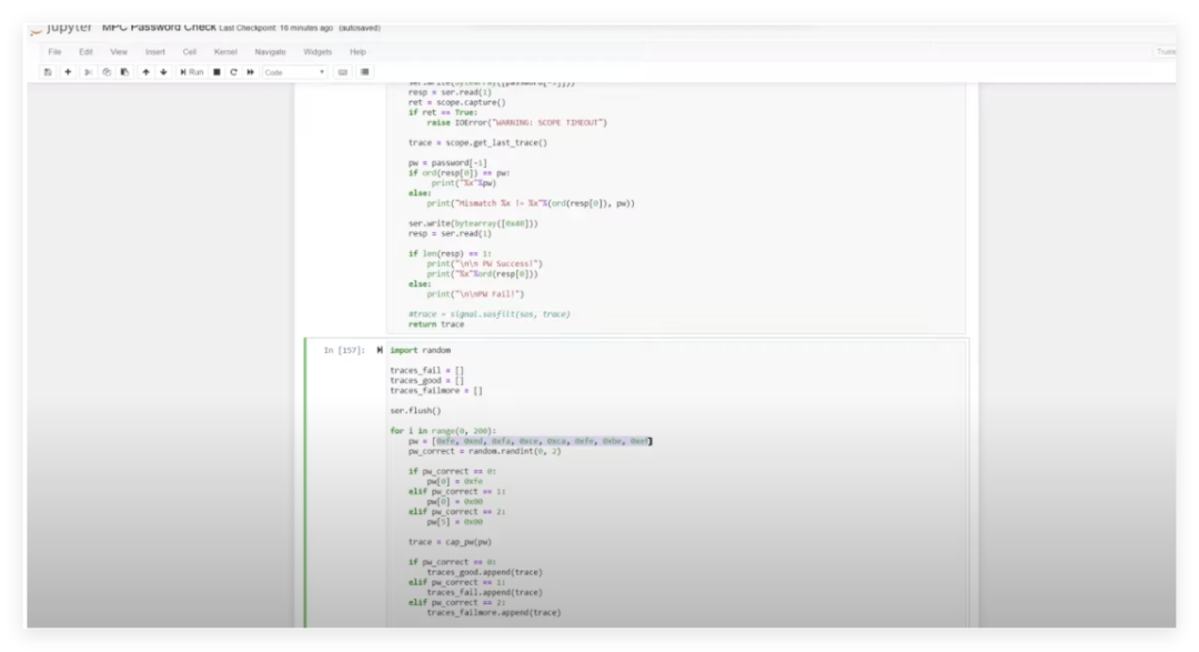
During the testing process, we sent invalid passwords to the device and monitored its responses, using the ChipWhisperer system to capture power characteristic differences. Analysis revealed that the correct password “feed face cafe beef” produced a unique four-peak waveform, while the waveform for the incorrect password was distinctly different.
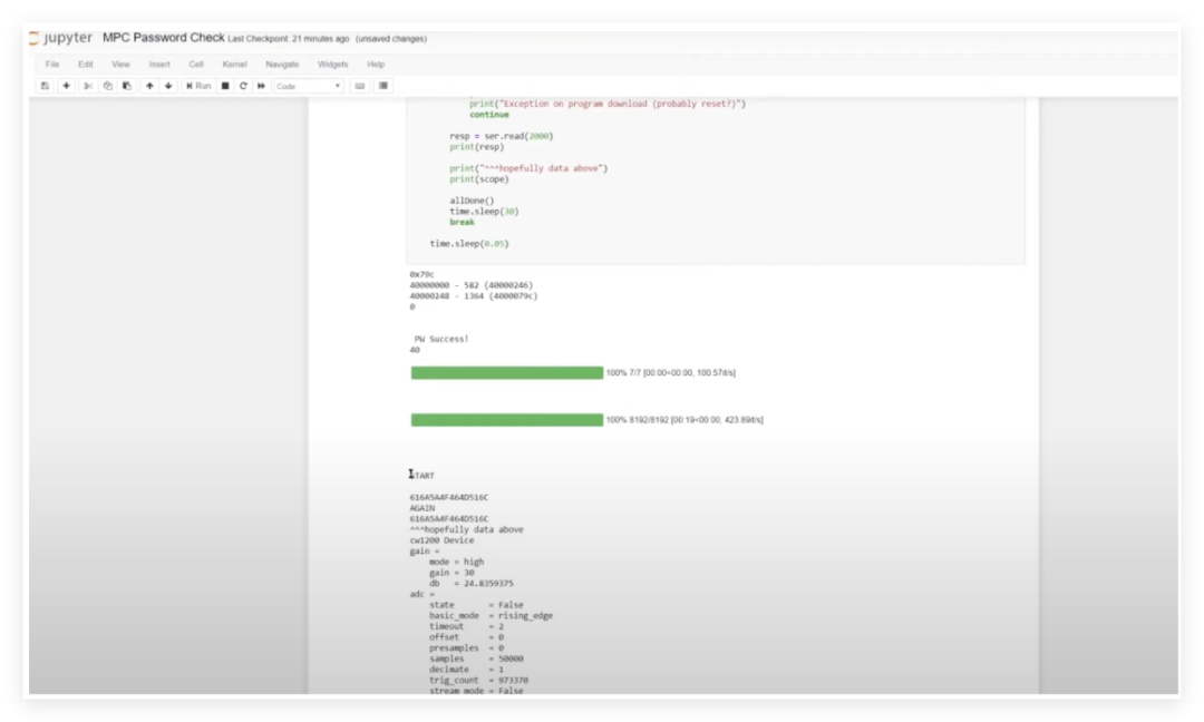
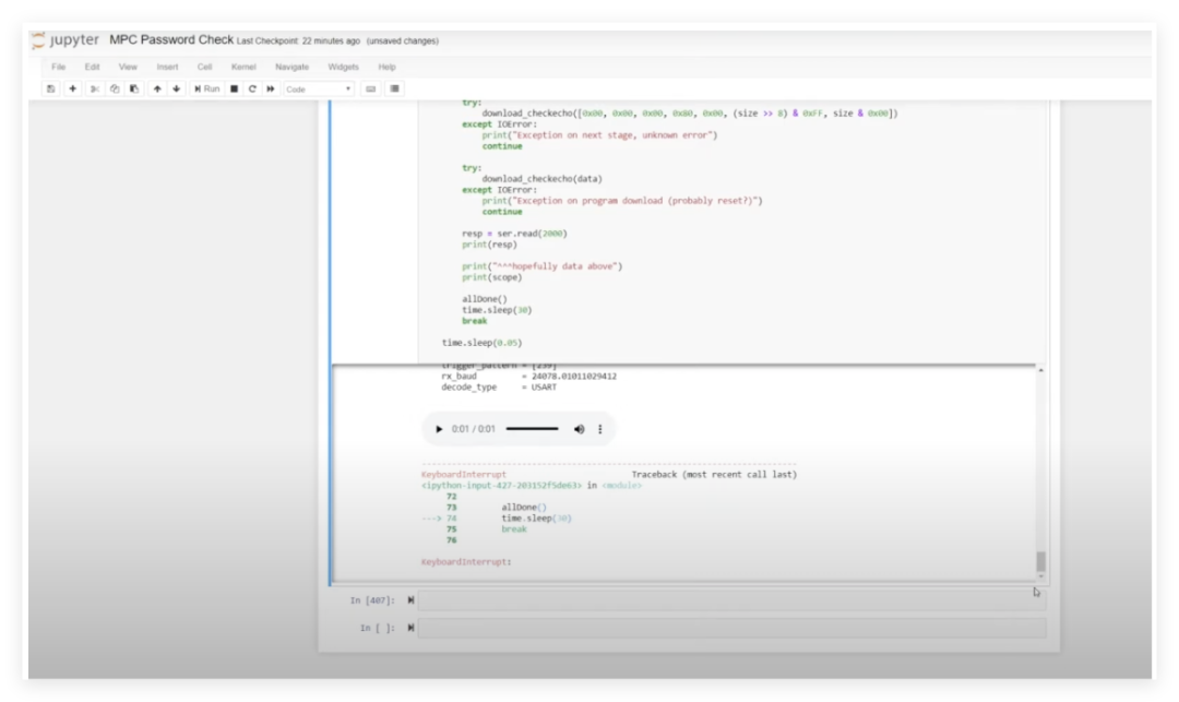
By configuring a 40MHz clock trigger signal, we injected faults at critical timing points during password verification, successfully causing the device to accept invalid passwords. Experimental data shows that this method can reliably extract the device’s unique boot password. Verification found that different ECUs use independent random passwords, effectively enhancing security. The JTAG interface of the current slot device is damaged, and the next step will be to optimize fault injection parameters to adapt to different hardware environments. This research provides important references for automotive electronic security assessment.

This experiment demonstrates that even if the ECU has customized password protection enabled, electromagnetic fault injection can still effectively bypass hardware security mechanisms. This vulnerability highlights the potential risks of automotive electronics at the physical security level. This experiment confirms the practical value of electromagnetic fault injection in automotive electronic security assessment, as many automotive functional safety standards now include tests such as fault injection.It is worth noting that the main control chip used in this ECU is an older chip that did not have HSM (Hardware Security Module) at the time. HSM is a computer device used to protect and manage keys and sensitive data used in strong authentication systems while providing related cryptographic operations. Nowadays, almost all main controls have HSM, making cracking a very difficult task. However, cracking and protection, vulnerabilities and fixes have always been “good friends”; as people pay more attention to security, many chips have begun to develop defenses from the ground up, and corresponding technologies are gradually iterating.
· END ·
Follow the subscription account under EEWorld: "Automotive Development Circle"
Reply "DS" to receive the complete information of "DeepSeek: From Beginner to Expert"

Scan the code to add the assistant and reply “join group”
Face-to-face communication with electronic engineers to exchange experiences