
Introduction
1. Functions of the Bootloader
2. How to Establish Reliable Bus Communication?
3. Parsing Programming Files (S19/HEX/BIN)
4. NVM Driver Development
5. Other Key Points in Bootloader Development
a. Relationship between Bootloader and Application
b. Methods for Jumping from Bootloader to Application
c. Knowledge and Debugging Techniques Required for Bootloader Development
d. Download Methods for Bootloader and Application during Mass Production
Conclusion
Introduction
On one hand, with the continuous advancement of semiconductor technology (according to Moore’s Law), the logic functions integrated within MCUs are becoming increasingly complex, and memory sizes are growing larger. On the other hand, consumer demands for automotive energy efficiency (economic and regulatory requirements for emissions), comfort, connectivity, and safety (functional safety and information security) are rising, especially with the recent emergence of new energy vehicles, vehicle networking, and autonomous driving technologies, which have significantly accelerated the development of automotive electronic technology. The functions integrated within automotive electronic ECUs (Electronic Control Unit) are becoming increasingly complex, leading to a growing demand for bootloaders (BootLoader) to support remote (online) software upgrades (adding new features) and bug fixes. This article will detail the key points in the development of automotive electronic ECU BootLoaders for your learning.
1. Functions of the Bootloader
The BootLoader, as the name suggests, is a piece of code that resides in the non-volatile memory of the ECU. It runs every time the ECU is reset. It checks for remote program loading requests from the communication bus; if there is one, it enters bootloader mode, establishes bus communication with the program download end (usually a PC), receives the application program downloaded from the communication bus, parses its address and data code, runs the NVM (Non-Volatile Memory) driver to program it into the NVM, and verifies its integrity, thus completing the application program update. If there are no remote program loading requests from the communication bus, it directly jumps to the application reset entry function (reset interrupt ISR, also known as Entry_Point()—using Processor Expert in CodeWarrior projects or the Startup() function in standard CodeWarrior projects), running the application.
Based on this, the three main functions of the automotive ECU bootloader are as follows:
-
Establish reliable bus communication with the remote program download end to obtain the application program to be updated;
-
Parse the application programming files (S19/HEX/BIN) to obtain their addresses and program codes and data in the NVM;
-
Run the NVM driver to program the application code and data into the NVM and verify it;
2. How to Establish Reliable Bus Communication?
Common data buses for automotive ECUs include CAN and LIN, so the bootloader for automotive ECUs typically downloads data via CAN or LIN. Other buses can also be used, such as SPI or I2C (typical for some safety ECUs with safety monitoring functions, where the main MCU upgrades the program of the safety monitoring MCU) and Ethernet (for central control or fully LCD instrument ECUs based on Ethernet communication, as well as next-generation high-speed gateways and ADAS ECUs).
Tips:
a. Different ECUs use different communication buses, and the specific bus required depends on the actual application;
b. The communication bus is implemented by the MCU peripherals, so the bootloader must develop corresponding communication bus peripheral drivers to achieve basic data sending and receiving functions;
c. To ensure communication reliability, a complete communication protocol based on the communication bus must be developed. Mechanisms such as request commands, acknowledgments, block waits, and error retransmissions need to be established between the application download end and the bootloader— the bootloader completes different tasks based on different request commands and confirms whether the operation is complete (ACK) and whether the data is being transmitted correctly. If data errors occur (detected through checksums or ECC), automatic retransmission is required;
d. The application download end must develop GUI software based on VC, C#, QT, Labview, etc., on the PC to implement the required bus communication protocol, generally calling the API interfaces of the dynamic libraries (DLL) of corresponding bus devices, such as USB to CAN/LIN converters, to achieve data transmission and reception. Therefore, bootloader developers generally need to have some PC software development skills;
e. To achieve reliable data transmission, it is common to add source coding in the bus communication protocol, i.e., performing checksums or ECC calculations on valid data during transmission and sending the results along with the valid data in the communication data frame. Upon receiving the data frame, the bootloader checks the integrity of the valid data by performing the same checksum or ECC calculation and comparing the result with the received checksum or ECC value. Application programming files (S19/HEX/BIN) have corresponding checksum mechanisms, so direct transmission of programming file lines can be adopted; otherwise, the user needs to parse the programming file on the host PC first, then package the addresses, data, and codes into a custom communication protocol, which the bootloader must unpack. This can be cumbersome, but some OEMs have their own bootloader protocols for intellectual property protection, in which case the bootloader developer must follow the OEM’s requirements for development;
f. Some major OEMs require their ECU suppliers to develop bootloaders based on UDS and other bus diagnostic protocols. UDS specifies corresponding CAN IDs for bootloader use, so the bootloader project in such ECUs must include the corresponding UDS protocol stack;
3. Parsing Programming Files (S19/HEX/BIN)
The programming file formats generated by different MCU software development IDEs may vary, but S19, HEX, and BIN files can be converted to each other. Therefore, only one programming file parsing program needs to be developed in the bootloader, while others can be converted using corresponding conversion tools on the host PC;
The purpose of parsing the programming file is to obtain the application program’s code and data and their storage addresses in the NVM;
To parse the programming file, one must first understand its encoding format and principles. Common S19, HEX, and BIN file format descriptions can be referenced at the following Wikipedia links:
-
HEX File: https://en.wikipedia.org/wiki/Intel_HEX
4. NVM Driver Development
The NVM of the ECU generally includes EEPROM or Data-Flash integrated within the MCU for data storage, and Code-Flash/Program-Flash for storing program codes/data, as well as external NOR Flash or NAND-Flash for MPU expansion. The NVM driver includes basic operations such as erasing, programming, and verifying the NVM, as well as encryption, decryption, protection, and unprotection operations.
Tips:
a. The EEPROM/D-Flash and C_Flash/P-Flash in the integrated NVM of the MCU generally belong to different blocks, so NVM drivers can directly operate on Flash to erase and program EEPROM/D-Flash;
b. NVM drivers typically run an NVM command sequence, where different NVM operation command codes, programming data, and target addresses are provided through the NVM controller registers. A typical NVM command sequence is as follows (Freescale’s S12(X) series MCU Flash write command sequence):
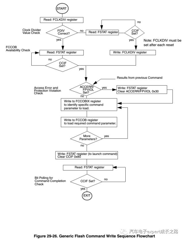
c. Since the working speed of NVM is generally lower than the CPU core frequency and bus frequency, the NVM must be initialized before running the NVM driver, setting the divider to the required normal operating frequency range;
d. The NVM driver cannot operate on the same block of NVM to erase and program itself, as this would cause a read while write bus access conflict (each NVM block has only one data bus, and can only perform read or write at one time, not both). Therefore, for MCUs with only one block of Flash, the NVM driver must be called in RAM to erase and program itself, and during the launch of the Flash command to wait for the command to complete, all global interrupts must be disabled to prevent peripheral interrupt responses, as accessing the interrupt vector and running the interrupt ISR would also access Flash.
To enable interrupts, the interrupt vector table must be relocated to RAM or an NVM block (EEPROM/D-Flash), and the corresponding interrupt ISR must also be copied to other RAM or NVM blocks (of course, the interrupt vector table must also be updated to guide the new interrupt ISR);
e. Due to the requirements mentioned in b, it is common to copy the bootloader’s NVM driver to run in the MCU’s RAM. This can either complete the NVM copy to RAM or just copy the NVM command launch to execute a few instructions in RAM while other operations (such as filling in NVM operation commands, writing programming addresses and data, etc.) do not write data to NVM over the data bus;
f. The NVM driver resides in Flash, and if unexpected program behavior such as stack overflow occurs, it may lead to accidental erasure or modification of NVM content. Therefore, it is necessary to protect critical data or code (such as the bootloader itself) to prevent accidental modification, or a safer method is not to store the NVM driver in NVM, but to download it to RAM for execution at the beginning of the bootloader via the host PC, and clear that RAM area after the bootloader ends to avoid data loss and modification due to accidental execution of the NVM driver.
g. Generally, MCU manufacturers provide NVM driver libraries for their MCUs, which users can use to perform NVM operations. If it is a Freescale/NXP automotive-grade MCU, the CodeWarrior IDE can also generate corresponding NVM drivers using the integrated Processor Expert;
5. Other Key Points in Bootloader Development
a. Relationship between Bootloader and Application
-
The bootloader and application are two complete MCU software projects, each with its own startup code, main() function, linker files, peripheral drivers, and interrupt vector tables;
-
Therefore, the linker files for the bootloader and application must independently allocate the NVM address space without overlap, but there are no constraints on RAM allocation, as both can use the entire RAM space since jumping to the application project will reinitialize RAM;
-
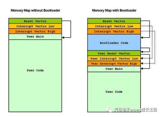
The bootloader must use the MCU’s default interrupt vector table, as the MCU always executes from the reset vector address in its default interrupt vector table after each reset. The application program’s interrupt vector must be offset (through the corresponding interrupt vector offset register, such as the IVBR register for S12(X) series MCUs or the SCB->VTOR register for ARM Cortex M series MCUs); while the NVM (P-Flash) erasure is performed sector-wise, so to fully utilize the NVM (P-Flash) space, the bootloader is partitioned into several NVM (P-Flash) sectors that include the default interrupt vector table (the last few sectors of NVM for S12(X) series MCUs, or several sectors starting from address 0 for ARM Cortex M series MCUs);
b. Methods for Jumping from Bootloader to Application
After developing and using the bootloader, every time the ECU is reset, the bootloader will run first. If there are no remote application download requests, it will directly jump to the application reset function address. There are two issues to consider:
How to obtain the application reset function address: There are methods: 1) Fix the application reset startup function address through the linker file; 2) Obtain it from the application interrupt vector table’s reset vector address; Recommended method 2): due to its flexibility, after each application change, there is no need to worry about the specific address where the application reset function is compiled into NVM; just extract the reset vector from the application interrupt vector table to run;
Typical method is as follows (assuming the application interrupt vector table base address register IVBR for S12(X) series MCU is 0x7F):
typedef void (*near tIsrFunc)(void);/* ISR prototype definition */
word *Ptr; /*pointer used for ISR vector fetch*/
Ptr = (word *)0x7FFE; /*get the ISR vector from the interrupt vector table of APP project */
((tIsrFunc)(*Ptr))(); /*convert and run*/
Jump Timing: There are methods: 1) After the bootloader updates the application and verifies its integrity, restore the used peripherals (such as CAN/LIN communication bus modules, timers, GPIO, etc.) to their default state after reset, and then jump directly; 2) After the bootloader updates the application and verifies its integrity, wait for the watchdog timer to timeout and reset, jumping after the bootloader initially checks for no remote application download requests; Recommended method 2): because method 1) may have differences in the MCU’s hardware environment when jumping to the application reset startup function compared to directly running the application, while method 2) with the watchdog reset is a hardware reset, which resets most peripherals (analog, clock, and peripheral) circuits, making it closer to the situation of directly running the application.
c. Knowledge and Debugging Techniques Required for Bootloader Development
First, developing a bootloader requires a clear understanding of the RAM and NVM resources used by the ECU, and then partitioning them to ensure that the NVM allocation for the application and bootloader does not overlap. Therefore, it is essential to understand the usage and writing rules of the linker files in the software development tool IDE used;
Specific references can be found in:CodeWarrior IDE usage tips on prm linker file details (custom memory partitioning and custom RAM data initialization and running functions in RAM)
Secondly, it is necessary to determine whether the interrupt vector table offset is successful, and the addresses and sizes of the copied NVM driver, so it is essential to master the specific information in the map file of the compilation and linking results of the software development tool IDE used;
Specific references can be found in: CodeWarrior IDE usage tips on map file details
Additionally, mastering how to redirect NVM functions (separating the storage address and runtime address of function program codes) to execute in RAM is also very useful;
Tips:
When developing the application, it is necessary to debug it separately to ensure its functionality is normal. Although the peripheral interrupt vector table has been offset, the reset vector must be placed in the address of the default interrupt vector table; otherwise, it cannot run normally after downloading, as if the application reset vector is placed in the offset application interrupt vector table, the default reset vector content will be 0xFFFF (the state after Flash erasure), and the CPU core will fetch instructions from address 0xFFFF, which is not the actual project startup function, leading to continuous illegal address resets. After the application development is completed, the reset vector can be offset to the application interrupt vector to avoid conflicts with the bootloader project’s Flash addresses;
Finally, mastering the use of the debugger’s Hotsync or attach methods to load debugging information from the elf file for seamless debugging of the bootloader and application is also very practical, significantly improving the debugging efficiency of the bootloader;
Specific references can be found in: CodeWarrior IDE usage tips on bug locating techniques—hotsync and attach debugging
d. Download Methods for Bootloader and Application during Mass Production
It is recommended to merge the programming files generated by compiling and linking the bootloader and application, and use mass production tools (such as Cyclone programmers) for one-time downloading to improve production efficiency.
Conclusion
This article has detailed the general working principles and development key points of automotive electronic ECU bootloaders, applicable to all automotive electronic ECU bootloader development. Of course, different MCUs have different software development tools IDEs and CPU core interrupt handling mechanisms, so I will continue to release a series of articles introducing bootloader development examples for S12(X) series MCUs, MagniV S12Z series MCUs, Qorivva MPC56xx/57xx series MCUs, and KEA/S32K series MCUs, along with corresponding demo projects for reference and learning. Stay tuned!