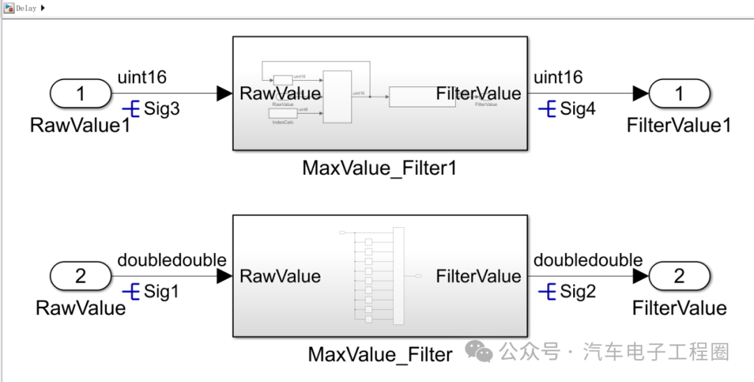
This article shares a case of exhausting RAM space, which is not complicated. The root cause comes from using one hundred delays to obtain100 consecutivesensor signal values, and then performing a maximum value operation, resulting in a software compilation error indicating that the RAM space exceeds the allocated space.Without further ado, let’s directly share the reasons behind the delay disaster.1 Application of DelayThe ECU low-level software obtains the AD values of the sensors and passes them to the application software model without any filtering. At this point, the application software model needs to take the maximum value from the 100 consecutive values for subsequent module use. To simplify the problem, let’s only take 10 consecutive values for processing. An obvious and miraculous method is to use the delay module as shown in the figure below to obtain these 10 values and then process them with the maximum value module.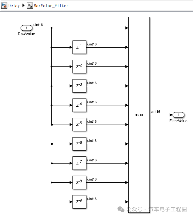 Upon simulation, the results were as expected, with no issues. If we do not pay attention to the generated code, after compiling and flashing it into the ECU, the results are also as expected, so we proceeded with this method. However, if the data volume is increased by 10 or even 100 times, will this method still work? Is it still acceptable?Don’t rush, I will configure the code generation and then generate the code as shown below:
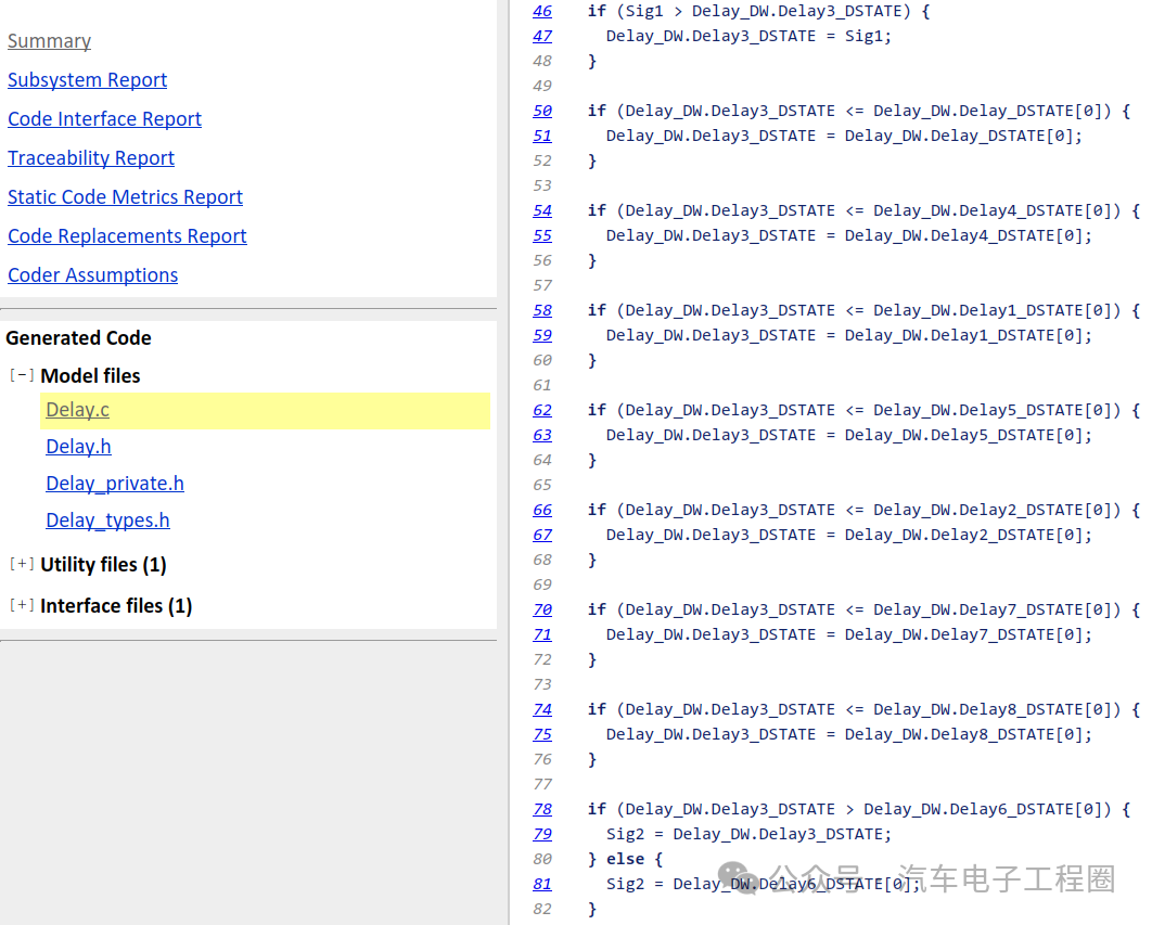
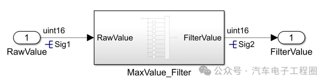 Note the first part of the generated code, as shown in the figure below, which is the comparison operation of these 10 signals: if signal 1 is compared withsignal2, thensignal2 is taken; next,signal2 is compared withsignal3, thensignal2 is taken; until it compares with signal 10, thus obtaining the maximum value as output.
 Note the second part of the generated code, which processes the values of 10 consecutive signals. Notice how it is more complex and cumbersome than expected, especially starting from delay[5] in the for loop. In fact, line 95 can be considered as the for loop for i=1, resulting in approximately 55 assignment operations overall.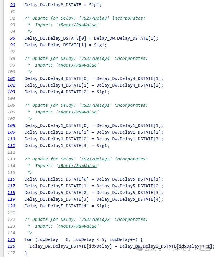
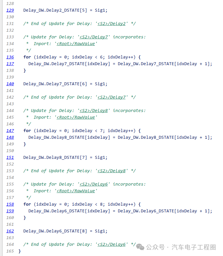 If it were 100 consecutive values, that would require 5500 assignment operations. Do you think this is acceptable? The actual situation is that problems arise either from direct compilation errors or from the software resetting.2 Replacing the Use of DelayI personally do not like using stateflow, so I will share a modeling method that can solve such problems. The overall idea is to use a buffer to store consecutive values and then use a for loop to compare and obtain the maximum value, as shown below:
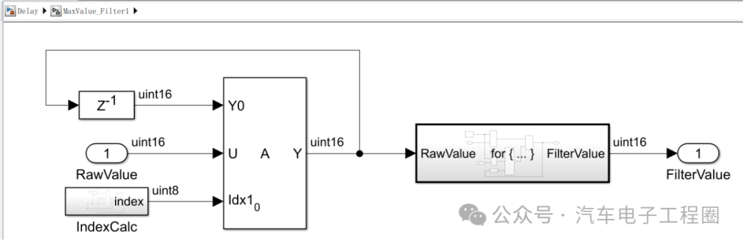 There are three key points:
- Counter — design a rolling array index.
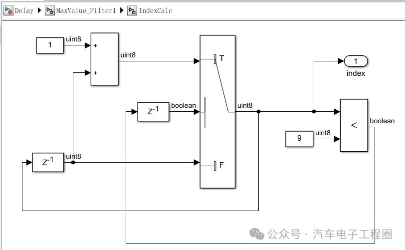
- Assignment module — update array values (store one and replace the corresponding one).
- For loop module — compare all elements of the array within a cycle to obtain the maximum value.
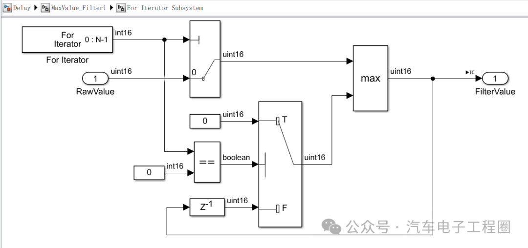 Finally, let’s take a look at the code generated by this method, as shown below:
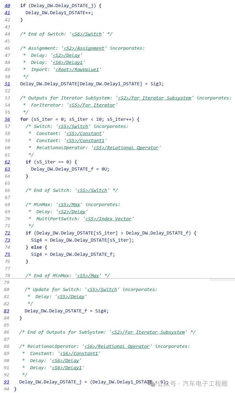 From the generated code, it can be seen that the number of assignment operations has been greatly reduced, from 55 assignments to just 1. Of course, this may not be the best optimization solution; it is merely a personal suggestion for addressing the delay issue.3 ConclusionDeveloping ECU software models may seem simple at times, but the underlying principles are worth exploring, especially when encountering problems. There is a saying that one regrets not studying more when the time comes to use it; thus, it is essential to study more regularly. Upon closer inspection, there are no advanced techniques involved; it is merely a combination of basic modules, simulation, and remembering that simulation is crucial, but analyzing the generated code is equally important, as the ECU operating mechanism differs from the Simulink simulation environment. OK, this concludes the analysis and solution of a practical application problem, and the next article will continue…
 Creating content is not easy, so please like, save, and follow.!( Qian Yixing Renamed Automotive Electronics Engineering Circle) Automotive R&D group chat, interested friends please add the group owner: prOmiseyes, with a note: company + position to join the group. Limited to automotive industry personnel.
Series of articles on ECU application layer software models are continuously updated, teaching you application layer development from scratch:
- Example 1 of building ECU application layer software model (qq.com)
- How to automatically generate code for ECU application layer software model 2 (qq.com)
- How to run ECU application layer software periodically 3 (qq.com)
- Code generation configuration related to ECU application layer software model and hardware 4 (qq.com)
- Data Dictionary DD of ECU application layer software model 5 (qq.com)
- Storage class of data dictionary in ECU application layer software model 6 (qq.com)
- Fixed-point implementation in ECU application layer software model 7 (qq.com)
- Five fixed-point implementation methods in ECU application software model 8 (qq.com)
- Custom storage class in ECU application layer software model 9 (qq.com)
- Summary of model generation code in ECU application layer software model 10 (qq.com)
- CAN reception in ECU application layer software model 11 (qq.com)
- Data stream of CAN message reception in ECU application layer software model 12
- How to leverage AI in ECU software development? Application of Kimi in MBD development environment 13
-
Unit test coverage CC, DC, and MCDC in ECU application layer software model 14
-
Application and principles of calibration quantity and observation quantity in ECU application layer model development 15
-
Use of for loop in ECU application layer model development 16
- Use of if-else in ECU application layer model development 17
- Initialization function in ECU application layer model development 18
-
Counter in ECU application layer model development 19
-
Basics of Assignment module in ECU application layer model development 20
-
Application of Delay module in ECU application layer model development 21
-
If-else VS switch-case in ECU application layer model development 22
- Simulink.Signal in data dictionary of ECU application layer model development 23