1. Introduction to ES8311
The ES8311 is a domestically produced low-power mono audio codec launched by Everest Semiconductor. It features high-performance low-power multi-bit ADC/DAC. It supports I2S/PCM master/slave mode serial data interfaces and I2C configuration interfaces. Both ADC and DAC are 24-bit with a sampling frequency of 8-96kHz (ADC signal-to-noise ratio 100dB, -93dB total harmonic distortion plus noise; DAC signal-to-noise ratio 110dB, -80dB total harmonic distortion plus noise). The operating voltage is 1.8V-3.3V, with playback and recording power consumption of 14mW, making it suitable for applications such as automotive, intercoms, and dash cameras. The operating temperature range is -40℃ to +105℃.
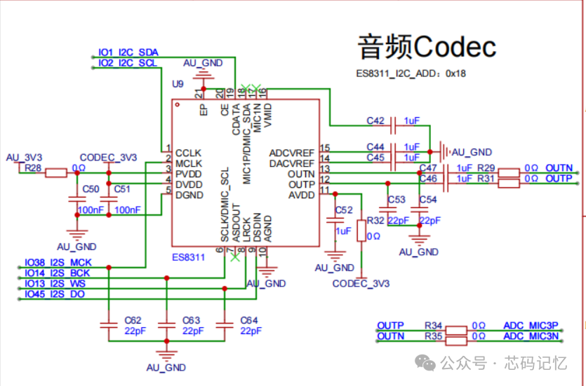
The hardware design diagram of the development board chip is as follows:
2. ESP32 Software Development
2.1. Project Creation
In VSCode, we click to create a new ESP-IDF project, selecting the sample_project as a template. Then we create a folder named components and a subfolder BSP to store the relevant chip driver code files. Since the control audio amplifier pin is from the IO expansion chip PCA9557, we need to create a PCA9557 folder under the BSP folder and then add a CMakeLists.txt in the BSP. The content is as follows:
set(src_dirs            PCA9557)
set(include_dirs            PCA9557)
set(requires            driver)
idf_component_register(SRC_DIRS ${src_dirs} INCLUDE_DIRS ${include_dirs} REQUIRES ${requires})
component_compile_options(-ffast-math -O3 -Wno-error=format=-Wno-format)
2.2. PCA9557 Driver Code
The PCA9557 uses I2C communication, so we need to initialize the I2C peripheral. The complete code is as follows:
#include "pca9557.h"
/** * @brief Read the value of the PCA9557 register * * @param reg_addr * @param data * @param len * @return esp_err_t */
esp_err_t pca9557_register_read(uint8_t reg_addr, uint8_t *data, uint32_t len){
return i2c_master_write_read_device(I2C_NUM, PCA9557_SENSOR_ADDR, ®_addr, 1, data, len, 1000 / portTICK_PERIOD_MS );
}
/** * @brief Write value to PCA9557 register * * @param reg_addr * @param data * @return esp_err_t */
esp_err_t pca9557_register_write_byte(uint8_t reg_addr, uint8_t data){
uint8_t data_buf[2] = {reg_addr, data};
return i2c_master_write_to_device(I2C_NUM, PCA9557_SENSOR_ADDR, data_buf, sizeof(data_buf), 1000 / portTICK_PERIOD_MS);
}
/** * @brief I2C_init * @note I2C initialization function * @return esp_err_t */
esp_err_t I2C_init(void){
i2c_config_t i2c_conf = {
.mode = I2C_MODE_MASTER,
.sda_io_num = I2C_SDA,
.sda_pullup_en = GPIO_PULLUP_ENABLE,
.scl_io_num = I2C_SCL,
.scl_pullup_en = GPIO_PULLUP_ENABLE,
.master.clk_speed = I2C_FREQ_HZ
};
i2c_param_config(I2C_NUM, &i2c_conf);
return i2c_driver_install(I2C_NUM, i2c_conf.mode, 0, 0, 0);
}
/** * @brief Initialize PCA9557 IO expansion chip * @param NULL */
void pca9557_init(void){
// Write default values to control pins DVP_PWDN =1 PA_EN = 0 LCD_CS = 1
pca9557_register_write_byte(PCA9577_OUTPUT_PORT, 0x05);
// Set PCA9557 chip IO0 IO1 IO2 as output, other pins remain as input
pca9557_register_write_byte(PCA9577_CONFIGURATION_PORT, 0xf8);
}
/** * @brief Set the output high or low level of a certain IO pin of PCA9557 * * @param gpio_bit * @param level High or low level * @return esp_err_t */
esp_err_t pca9557_set_output_state(uint8_t gpio_bit, uint8_t level){
uint8_t data;
esp_err_t res = ESP_FAIL;
pca9557_register_read(PCA9577_OUTPUT_PORT, &data, 1);
res = pca9557_register_write_byte(PCA9577_OUTPUT_PORT, SET_BITS(data, gpio_bit, level));
return res;
}
/** * @brief Control PCA8557_LCD_CS pin output high or low level * * @param level 0: output low level 1: output high level */
void lcd_cs(uint8_t level){
pca9557_set_output_state(LCD_CS_GPIO, level);
}
/** * @brief Control PCA8557_PA_EN pin output high or low level * * @param level 0: output low level 1: output high level */
void pa_en(uint8_t level){
pca9557_set_output_state(PA_EN_GPIO, level);
}
/** * @brief Control PCA8557_DVP_PWDN pin output high or low level * * @param level 0: output low level 1: output high level */
void dvp_pwdn(uint8_t level){
pca9557_set_output_state(DVP_PWDN_GPIO, level);
}2.3. Writing the Application Program
Referring to the official i2s_es8311 example, we first add the I2S initialization function in main.c as follows:
static esp_err_t i2s_driver_init(void){
    i2s_chan_config_t chan_cfg = I2S_CHANNEL_DEFAULT_CONFIG(I2S_NUM, I2S_ROLE_MASTER);      // Default configuration for i2s channel
    chan_cfg.auto_clear = true; // Automatically clear data in DMA buffer
    ESP_ERROR_CHECK(i2s_new_channel(&chan_cfg, &tx_handle, NULL));
    i2s_std_config_t std_cfg = {
        .clk_cfg = I2S_STD_CLK_DEFAULT_CONFIG(EXAMPLE_SAMPLE_RATE),
        .slot_cfg = I2S_STD_PHILIPS_SLOT_DEFAULT_CONFIG(I2S_DATA_BIT_WIDTH_16BIT, I2S_SLOT_MODE_STEREO),
        .gpio_cfg = {
            .mclk = I2S_MCK_IO,
            .bclk = I2S_BCK_IO,
            .ws = I2S_WS_IO,
            .dout = I2S_DO_IO,
            .din = I2S_DI_IO,
            .invert_flags = {
                .mclk_inv = false,
                .bclk_inv = false,
                .ws_inv = false,
            },
        },
    };
    std_cfg.clk_cfg.mclk_multiple = EXAMPLE_MCLK_MULTIPLE;
    ESP_ERROR_CHECK(i2s_channel_init_std_mode(tx_handle, &std_cfg));                    // Set i2s channel to standard mode
    ESP_ERROR_CHECK(i2s_channel_enable(tx_handle));                                     // Enable i2s channel
    return ESP_OK;
}
The initialization function for the ES8311 codec is as follows:
static esp_err_t es8311_codec_init(void){
    /* Initialize es8311 codec */
    es8311_handle_t es_handle = es8311_create(I2C_NUM, ES8311_ADDRRES_0);
    ESP_RETURN_ON_FALSE(es_handle, ESP_FAIL, TAG, "es8311 create failed");
    const es8311_clock_config_t es_clk = {
        .mclk_inverted = false,
        .sclk_inverted = false,
        .mclk_from_mclk_pin = true,
        .mclk_frequency = EXAMPLE_MCLK_FREQ_HZ,
        .sample_frequency = EXAMPLE_SAMPLE_RATE
    };
    ESP_ERROR_CHECK(es8311_init(es_handle, &es_clk, ES8311_RESOLUTION_16, ES8311_RESOLUTION_16));
    ESP_RETURN_ON_ERROR(es8311_sample_frequency_config(es_handle, EXAMPLE_SAMPLE_RATE * EXAMPLE_MCLK_MULTIPLE, EXAMPLE_SAMPLE_RATE), TAG, "set es8311 sample frequency failed");
    ESP_RETURN_ON_ERROR(es8311_voice_volume_set(es_handle, EXAMPLE_VOICE_VOLUME, NULL), TAG, "set es8311 volume failed");
    ESP_RETURN_ON_ERROR(es8311_microphone_config(es_handle, false), TAG, "set es8311 microphone failed");
    return ESP_OK;
}
The function to execute the I2S music playback task is as follows:
static void i2s_music(void *args){
    esp_err_t ret = ESP_OK;
    size_t bytes_write = 0;
    uint8_t *data_ptr = (uint8_t *)music_pcm_start;
    /* (Optional) Disable TX channel and preload the data before enabling the TX channel,     * so that the valid data can be transmitted immediately */
    ESP_ERROR_CHECK(i2s_channel_disable(tx_handle));
    ESP_ERROR_CHECK(i2s_channel_preload_data(tx_handle, data_ptr, music_pcm_end - data_ptr, &bytes_write));
    data_ptr += bytes_write;  // Move forward the data pointer
    /* Enable the TX channel */
    ESP_ERROR_CHECK(i2s_channel_enable(tx_handle));
    while (1) {
        /* Write music to earphone */
        ret = i2s_channel_write(tx_handle, data_ptr, music_pcm_end - data_ptr, &bytes_write, portMAX_DELAY);
        if (ret != ESP_OK) {
            /* Since we set timeout to 'portMAX_DELAY' in 'i2s_channel_write'               so you won't reach here unless you set other timeout value,               if timeout detected, it means write operation failed. */
            ESP_LOGE(TAG, "[music] i2s write failed, %s", err_reason[ret == ESP_ERR_TIMEOUT]);
            abort();
        }
        if (bytes_write > 0) {
            ESP_LOGI(TAG, "[music] i2s music played, %d bytes are written.", bytes_write);
        } else {
            ESP_LOGE(TAG, "[music] i2s music play failed.");
            abort();
        }
        data_ptr = (uint8_t *)music_pcm_start;
        vTaskDelay(1000 / portTICK_PERIOD_MS);
    }
    vTaskDelete(NULL);
}
The complete code in main.c is as follows:
#include <stdio.h>
#include <string.h>
#include "freertos/FreeRTOS.h"
#include "freertos/task.h"
#include "driver/i2s_std.h"
#include "esp_system.h"
#include "esp_check.h"
#include "es8311.h"
#include "pca9557.h"
#define EXAMPLE_RECV_BUF_SIZE   (2400)
#define EXAMPLE_SAMPLE_RATE     (16000)
#define EXAMPLE_MCLK_MULTIPLE   (384) // If not using 24-bit data width, 256 should be enough
#define EXAMPLE_MCLK_FREQ_HZ    (EXAMPLE_SAMPLE_RATE * EXAMPLE_MCLK_MULTIPLE)
#define EXAMPLE_VOICE_VOLUME    (70)
/* I2S port and GPIOs */
#define I2S_NUM         (0)
#define I2S_MCK_IO      (GPIO_NUM_38)
#define I2S_BCK_IO      (GPIO_NUM_14)
#define I2S_WS_IO       (GPIO_NUM_13)
#define I2S_DO_IO       (GPIO_NUM_45)
#define I2S_DI_IO       (-1)
static const char *TAG = "i2s_es8311";
static const char err_reason[][30] = {"input param is invalid",                                      "operation timeout"                                     };
static i2s_chan_handle_t tx_handle = NULL;
extern const uint8_t music_pcm_start[] asm("_binary_canon_pcm_start");
extern const uint8_t music_pcm_end[]   asm("_binary_canon_pcm_end");
/** * @brief i2s_driver_init *  * @return esp_err_t  */
static esp_err_t i2s_driver_init(void){
    i2s_chan_config_t chan_cfg = I2S_CHANNEL_DEFAULT_CONFIG(I2S_NUM, I2S_ROLE_MASTER);      // Default configuration for i2s channel
    chan_cfg.auto_clear = true; // Automatically clear data in DMA buffer
    ESP_ERROR_CHECK(i2s_new_channel(&chan_cfg, &tx_handle, NULL));
    i2s_std_config_t std_cfg = {
        .clk_cfg = I2S_STD_CLK_DEFAULT_CONFIG(EXAMPLE_SAMPLE_RATE),
        .slot_cfg = I2S_STD_PHILIPS_SLOT_DEFAULT_CONFIG(I2S_DATA_BIT_WIDTH_16BIT, I2S_SLOT_MODE_STEREO),
        .gpio_cfg = {
            .mclk = I2S_MCK_IO,
            .bclk = I2S_BCK_IO,
            .ws = I2S_WS_IO,
            .dout = I2S_DO_IO,
            .din = I2S_DI_IO,
            .invert_flags = {
                .mclk_inv = false,
                .bclk_inv = false,
                .ws_inv = false,
            },
        },
    };
    std_cfg.clk_cfg.mclk_multiple = EXAMPLE_MCLK_MULTIPLE;
    ESP_ERROR_CHECK(i2s_channel_init_std_mode(tx_handle, &std_cfg));                    // Set i2s channel to standard mode
    ESP_ERROR_CHECK(i2s_channel_enable(tx_handle));                                     // Enable i2s channel
    return ESP_OK;
}
/** * @brief es8311_codec_init * @note es8311 initialization * @return esp_err_t  */
static esp_err_t es8311_codec_init(void){
    /* Initialize es8311 codec */
    es8311_handle_t es_handle = es8311_create(I2C_NUM, ES8311_ADDRRES_0);
    ESP_RETURN_ON_FALSE(es_handle, ESP_FAIL, TAG, "es8311 create failed");
    const es8311_clock_config_t es_clk = {
        .mclk_inverted = false,
        .sclk_inverted = false,
        .mclk_from_mclk_pin = true,
        .mclk_frequency = EXAMPLE_MCLK_FREQ_HZ,
        .sample_frequency = EXAMPLE_SAMPLE_RATE
    };
    ESP_ERROR_CHECK(es8311_init(es_handle, &es_clk, ES8311_RESOLUTION_16, ES8311_RESOLUTION_16));
    ESP_RETURN_ON_ERROR(es8311_sample_frequency_config(es_handle, EXAMPLE_SAMPLE_RATE * EXAMPLE_MCLK_MULTIPLE, EXAMPLE_SAMPLE_RATE), TAG, "set es8311 sample frequency failed");
    ESP_RETURN_ON_ERROR(es8311_voice_volume_set(es_handle, EXAMPLE_VOICE_VOLUME, NULL), TAG, "set es8311 volume failed");
    ESP_RETURN_ON_ERROR(es8311_microphone_config(es_handle, false), TAG, "set es8311 microphone failed");
    return ESP_OK;
}
/** * @brief i2s_music * @note i2s music playback task * @param args  */
static void i2s_music(void *args){
    esp_err_t ret = ESP_OK;
    size_t bytes_write = 0;
    uint8_t *data_ptr = (uint8_t *)music_pcm_start;
    /* (Optional) Disable TX channel and preload the data before enabling the TX channel,     * so that the valid data can be transmitted immediately */
    ESP_ERROR_CHECK(i2s_channel_disable(tx_handle));
    ESP_ERROR_CHECK(i2s_channel_preload_data(tx_handle, data_ptr, music_pcm_end - data_ptr, &bytes_write));
    data_ptr += bytes_write;  // Move forward the data pointer
    /* Enable the TX channel */
    ESP_ERROR_CHECK(i2s_channel_enable(tx_handle));
    while (1) {
        /* Write music to earphone */
        ret = i2s_channel_write(tx_handle, data_ptr, music_pcm_end - data_ptr, &bytes_write, portMAX_DELAY);
        if (ret != ESP_OK) {
            /* Since we set timeout to 'portMAX_DELAY' in 'i2s_channel_write'               so you won't reach here unless you set other timeout value,               if timeout detected, it means write operation failed. */
            ESP_LOGE(TAG, "[music] i2s write failed, %s", err_reason[ret == ESP_ERR_TIMEOUT]);
            abort();
        }
        if (bytes_write > 0) {
            ESP_LOGI(TAG, "[music] i2s music played, %d bytes are written.", bytes_write);
        } else {
            ESP_LOGE(TAG, "[music] i2s music play failed.");
            abort();
        }
        data_ptr = (uint8_t *)music_pcm_start;
        vTaskDelay(1000 / portTICK_PERIOD_MS);
    }
}

void app_main(void){
    printf("i2s es8311 codec example start\n-----------------------------\n");
    I2C_init();  // I2C initialization
    /* Initialize i2s peripheral */
    if (i2s_driver_init() != ESP_OK) {
        ESP_LOGE(TAG, "i2s driver init failed");
        abort();
    } else {
        ESP_LOGI(TAG, "i2s driver init success");
    }
    /* Initialize i2c peripheral and config es8311 codec by i2c */
    if (es8311_codec_init() != ESP_OK) {
        ESP_LOGE(TAG, "es8311 codec init failed");
        abort();
    } else {
        ESP_LOGI(TAG, "es8311 codec init success");
    }
    pca9557_init();         // IO expansion chip initialization
    pa_en(1); // Enable audio
    /* Play a piece of music in music mode */
    xTaskCreate(i2s_music, "i2s_music", 4096, NULL, 5, NULL);
}
2.4. Improving the Project and Compiling for Debugging
The official ESP32 components include the ES8311 driver component. We will copy the idf_component.yml file from the official i2s_es8311 example and place it in the main folder of our created project. Looking at this file, we only need to define the idf version and es8311; other conditional compilations related to the development board can be removed. The modified file content is as follows:
## IDF Component Manager Manifest File
dependencies:
  idf: "^5.0"
  espressif/es8311: "^1.0.0"
We also need to copy the audio file canon.pcm from the official example into our project’s main folder. In the CMakeLists.txt file under main, we will use EMBED_FILES to add the canon.pcm file to the compiler. The changes are as follows:
idf_component_register(SRCS "main.c"
                    INCLUDE_DIRS "."
                    EMBED_FILES "canon.pcm")
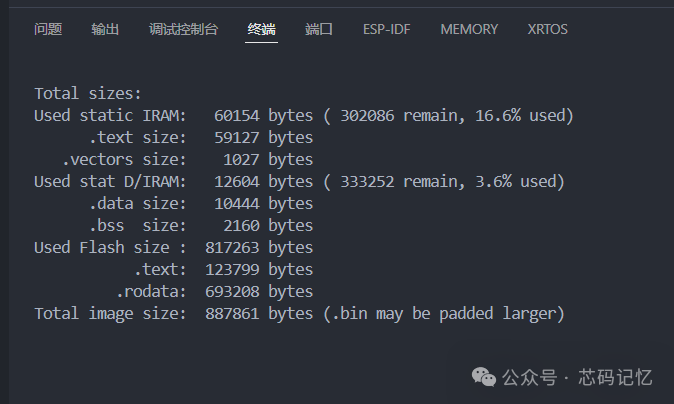
Finally, click the build project button to compile the project, and the compilation will complete successfully as shown in the following image:
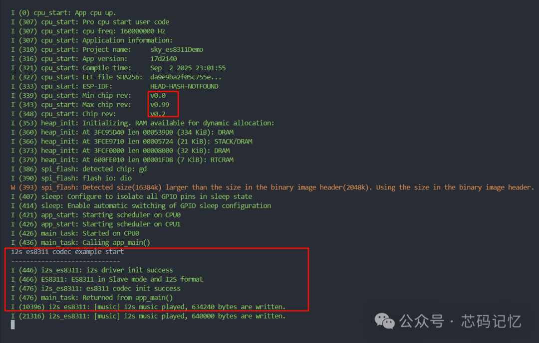
The debugging log is shown in the following image:
Related project code repository path:https://gitee.com/wei-xiangyun/esp32-chip.git