Modbus Master to Modbus Slave with Different Baud Rates– Converter– Guangzhou Xinyu IoT
Author: Zou Wuyi Mobile185-020-77899 Email: [email protected]
1 Features:
The configurable “Modbus Slave/Modbus Slave – Converter” has the following features:
• Electrical isolation between Modbus ports.
• Can be mounted on a 35mm DIN rail;
• Power supply: 8…24V AC or 12…35V DC;
• Operating temperature range: -40°C to +85°C.
Configuration:
You need to install the Compositor SW67146 software on your computer to perform the following operations:
• Define the parameters of the Modbus Slave (Port 0);
• Define the parameters of the Modbus Slave (Port 1);
• Define the Modbus Slave devices accessible by each Master;
• Define the parameters of the Modbus Master;
• Update the device.
2 New Configuration / Open Configuration:
The “New Configuration” button will create a folder containing the configuration information for the entire device.
The device configuration can also be imported or exported:
To clone the programmable “Modbus Master / Modbus Multi-Slave Converter” configuration for configuring another device in the same way, you must keep this folder and all its contents;
To clone a project for a different version of that project, simply copy the project folder and rename it, then use the “Open Configuration” button to open the new folder.
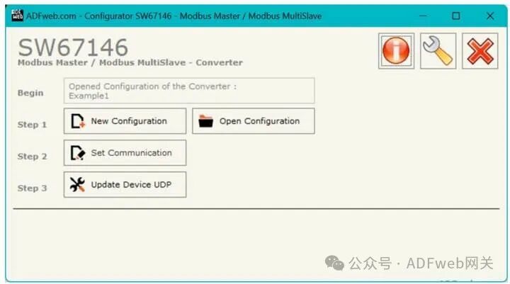
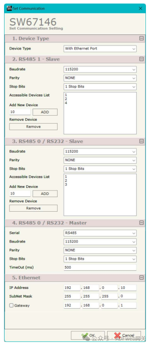
3 Set Communication: This section defines the basic communication parameters for the three-port Modbus system. Pressing the “ Set Communication” button in the main window of SW67146 (Figure 2) will pop up the “ Set Communication” window (Figure 3). In the “ Device Type” section, you can select the type of device to use:
- No Ethernet port;
- With Ethernet port. The “RS485 1 – Slave” field means:
- The “ Baud Rate” field is used to define the baud rate for Modbus;
- The “ Parity” field is used to define the parity method for Modbus;
- The “ Stop Bits” field is used to define the number of stop bits for the serial line;
- The “ Accessible Device List” field is used to define the Modbus Slave IDs accessible by the host connected to Port 1. The “RS485 0 / RS232 – Slave” field means:
- The “ Baud Rate” field is used to define the baud rate for Modbus;
- The “ Parity” field is used to define the parity method for Modbus;
- The “ Stop Bits” field is used to define the number of stop bits for the serial line;
- The “ Accessible Device List” field is used to define the Modbus Slave IDs accessible by the host connected to Port 0.
The meanings of the fields for “RS485 0 / RS232 – Master” are as follows:
• In the “Serial Port” field, you can select the serial port used by the Master Modbus, options include “RS232” and “RS485.”
• In the “Baud Rate” field, you can define the baud rate for the Modbus Master.
• In the “Parity” field, you can define the parity method for the Modbus Master.
• In the “Stop Bits” field, you can define the number of stop bits for the serial line.
• In the “Timeout” field, the maximum time the device waits for a response from the polled Slave is set.
The meanings of the fields in the “Ethernet” section are as follows:
• In the “IP Address” field, you can define the IP address of the converter’s Ethernet port.
• In the “Subnet Mask” field, you can define the subnet mask of the converter’s Ethernet port.
• In the “Gateway” field, you can define the default gateway for the network. This feature can be enabled or disabled by checking the checkbox, which is used for external network access.