The RS-485 bus is widely used in communication, industrial automation, and other fields. In practical applications, we often encounter the question of whether to add pull-up and pull-down resistors and what size of resistors is appropriate. Below, we will conduct a detailed analysis of these issues.
1. Why Are Pull-Up and Pull-Down Resistors Needed?
1. When the differential voltage on the 485 bus is greater than +200mV, the 485 transceiver outputs a high level;
2. When the differential voltage on the 485 bus is less than -200mV, the 485 transceiver outputs a low level;
3. When the voltage on the 485 bus is between -200mV and +200mV, the 485 transceiver may output either a high or low level. However, it generally tends to stay in one level state. If the output of the 485 transceiver is low, this represents a start bit for UART communication, which can lead to abnormal communication.
When the 485 bus is open (the 485 transceiver is disconnected from the bus) or in an idle state (all 485 transceivers are in receive mode and no transceiver is driving the bus), the differential voltage of the 485 bus is essentially 0, putting the bus in an uncertain state. Moreover, due to the design of current 485 chips, which aim to increase the number of nodes on the bus, the input impedance is relatively high, for example, an input impedance of 1/4 unit impedance or 1/8 unit impedance (where the unit impedance is 12kΩ, and 1/4 unit impedance is 48kΩ). When the pins are left floating, they are susceptible to electromagnetic interference.
Therefore, to prevent the aforementioned situations on the 485 bus, pull-up and pull-down resistors are typically added on the 485 bus (usually a pull-up resistor is connected to A, and a pull-down resistor is connected to B). If using an isolated RS-485 transceiver module (e.g., RSM485PCHT), since the module has built-in pull-up and pull-down resistors (for RSM485PCHT, the built-in pull-up and pull-down resistors are 24kΩ), generally, no additional pull-up and pull-down resistors need to be added externally.
When encountering signal reflection issues, matching resistors are usually added to avoid signal reflection. For example, in a 1-to-1 communication scenario, as shown in Figure 1. Since the 485 bus typically uses twisted pairs with a characteristic impedance of 120Ω, 120Ω termination resistors are added at both ends of the 485 bus to avoid signal reflection problems.
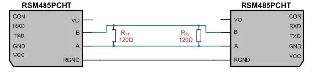 Figure 1: Communication Circuit of Two RSM485PCHT Modules
According to the specific parameters of RSM485PCHT (as shown in Table 1), the equivalent circuit can be obtained as shown in Figure 2, where RPU and RPD are the pull-up and pull-down resistors added internally by the module on the 485 bus, and RIN is the input impedance of the module.
Table 1: RSM485PCHT Parameters
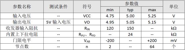
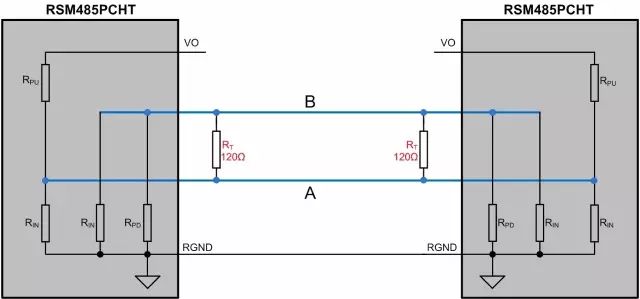 Figure 2: RSM485PCHT Communication Equivalent Circuit Diagram
When both modules are in receive mode, the following formulas can be derived for nodes A and B based on Kirchhoff’s current law:
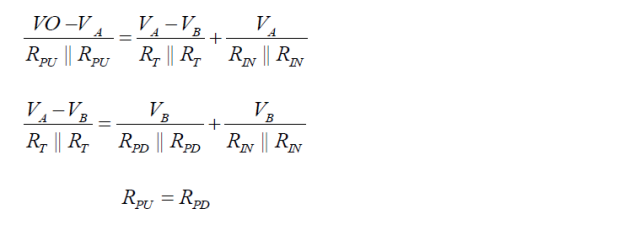
Based on the above formulas, the differential voltage between A and B can be calculated as:
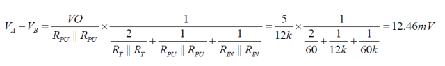
At this point, the module is in an uncertain state, and the module’s receiver may output either a high or low level. Therefore, it is necessary to add pull-up and pull-down resistors externally to ensure that the module does not remain in an uncertain state when idle.
3. How to Select Pull-Up and Pull-Down Resistors?
Assuming the output power supply voltage V¬O of the module is the same, since RGND is connected together, the internal pull-up resistors of the module can be considered to be in parallel. For ease of explanation, the circuit in Figure 2 is organized as shown in Figure 3, where one set of pull-up and pull-down resistors can be added externally, or pull-up and pull-down resistors can be added to each module. For convenience of explanation, we add one set of pull-up and pull-down resistors on the 485 bus.
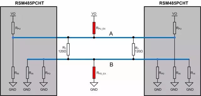 Figure 3: RSM485PCHT Communication Equivalent Circuit Diagram
Where:
RPU is the internal pull-up resistor of the module, RPD is the internal pull-down resistor of the module, which in this example is 24kΩ;
RIN is the input impedance of the module, which in this example is taken as the minimum value of 120kΩ;
RT is the termination resistor, which in this example is taken as 120Ω;
RPU_EX is the external pull-up resistor added to the module, and RPD_EX is the external pull-down resistor added to the module;
Since the threshold level of RSM485PCHT is -200mV to +200mV, generally leaving a voltage margin of 100mV or 200mV, in this example, a voltage margin of 100mV is reserved. Based on the previously derived differential voltage formula, the following calculation formula can be obtained:
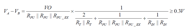
Since RPU = 24kΩ, we can obtain RPU_EX = RPD_EX = 461.9Ω. Since the calculated resistor value is the maximum value, we can choose to add only one set of 410Ω or 390Ω pull-up and pull-down resistors on the 485 bus, or add two sets of 910Ω pull-up and pull-down resistors.
4. How to Verify the Value of Pull-Up and Pull-Down Resistors?
The above calculations only consider the idle state of the 485 bus and do not take into account the driving capacity of the 485 transceiver and the power consumption of the components used. The smaller the external pull-up and pull-down resistors, the higher the differential voltage of the 485 bus can be maintained in an idle state, but at the same time, the power consumption of the termination resistors and pull-up and pull-down resistors also increases, thus requiring a higher driving capacity from the 485 transceiver. If this exceeds the driving capacity of the 485 transceiver, it may also lead to communication failures.
According to the RS-485 standard, when the input impedance of the receiver is unit impedance (minimum 12k), a maximum of 32 nodes can be connected to the bus, and the maximum differential load of 485 is 54Ω. At this time, the minimum differential output voltage is 1.5V.
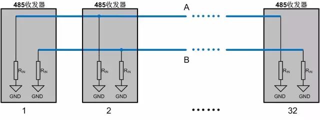 Figure 4: 485 Bus Connecting 32 Nodes Equivalent Diagram
As shown in Figure 4, we can see that when there are 32 nodes connected on the 485 bus, the common mode load of bus A or B is:
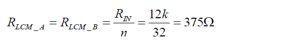
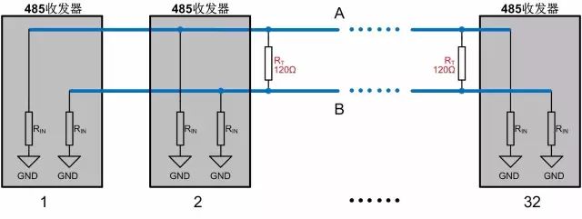 Figure 5: 485 Bus Adding Termination Resistor Equivalent Diagram
Therefore, when the number of nodes on the 485 bus reaches the maximum and the termination resistors are added, the differential load of the 485 bus is still greater than 54Ω. According to the RS-485 standard, the minimum differential output voltage is 1.5V.
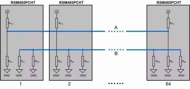 Figure 6: RSM485PCHT 64 Nodes Equivalent Diagram
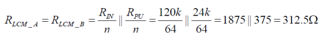
Taking RSM485PCHT as an example to illustrate the situation of adding pull-up and pull-down resistors, as shown in Figure 6, the common mode load of bus A or B is:
Actual testing of the above situation shows that the minimum differential voltage output is 3.02V, which is far greater than the minimum differential output voltage of 1.5V specified by the RS-485 standard.
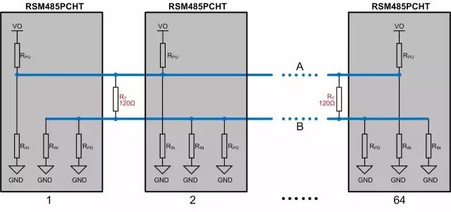 Figure 7: RSM485PCHT 64 Nodes Adding Termination Resistors Diagram
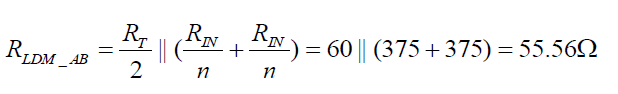
When adding termination resistors to the 485 bus, it can be seen that the common mode load of bus A or B does not change, while the differential impedance shows a significant change. At this time, the differential load is:
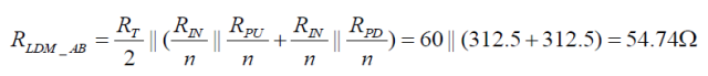
The calculated differential load is slightly greater than the maximum load specified by the RS-485 standard of 54Ω. We performed actual tests on RSM485PCHT, and its output differential voltage is 1.58V, slightly greater than the minimum voltage specified by the standard.
When the differential load is 54Ω (the 485 bus is connected to two 120Ω termination resistors and the parallel value of the pull-up and pull-down resistors with the transceiver’s internal resistance is 270Ω), the differential output voltage of RSM485PCHT is 1.52V (measured value), which is basically the same as the RS-485 standard. When the differential load is 41.54Ω (the 485 bus is connected to two 120Ω termination resistors and the parallel value of the pull-up and pull-down resistors with the transceiver’s internal resistance is 135Ω), the differential output voltage of RSM485PCHT is around 1.17V (measured value). In this case, communication can still occur. However, the maximum differential load specified in the 485 transceiver chip manual is usually 54Ω, meaning that after adding two 120Ω termination resistors on the 485 bus, the parallel value of the pull-up and pull-down resistors with the transceiver’s input impedance should be greater than 270Ω. At the same time, to ensure stable and reliable communication, the parallel value of the pull-up and pull-down resistors with the transceiver’s input impedance should generally be greater than 375Ω.
5. Conclusion
1. The communication line should use shielded twisted pairs, and the shielding layer should be grounded at a single point;
2. When we do not encounter signal reflection issues, try not to use termination resistors;
3. If using termination resistors, we can adjust the voltage value of the 485 bus in idle state through pull-up and pull-down resistors to ensure it does not fall within the threshold level (-200mV to +200mV or -200mV to -40mV);
4. When we add pull-up and pull-down resistors, the parallel value of the pull-up and pull-down resistors with the transceiver’s input impedance should be greater than 375Ω.
Recommended Reading:
Historical Changes and Differences from ASCII Code to Unicode to UTF-8
What Technologies Are Involved in Through-Hole and Back Drilling in PCB Manufacturing?
Follow the public account ‘strongerHuang’, reply ‘1024’ in the background to see more wonderful content, or reply ‘Join Group’ to join Huang’s technical exchange group.

Long pressto recognize the QR code in the imageand follow