Source: Semiconductor Comprehensive
Author: Yuan Yuan De Yuan
This article introduces vehicle sensors and LiDAR technology.
1. Classification of Vehicle Sensors
Sensors used in autonomous driving systems are mainly divided into:
Optical cameras, millimeter-wave radar, ultrasonic sensors, and LiDAR (Light Detection and Ranging).
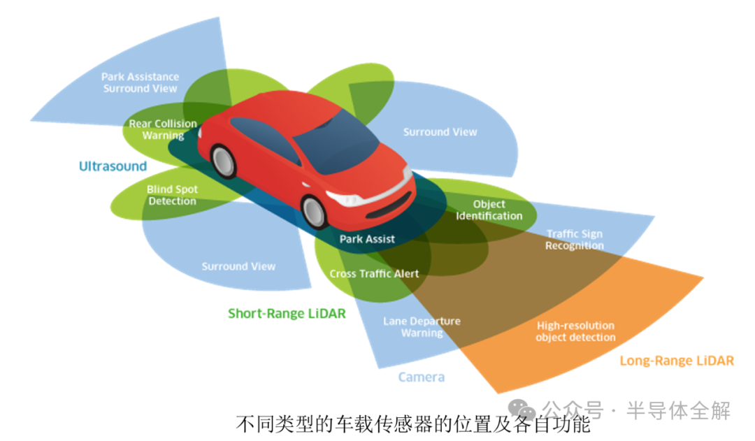
The positions and functions of different types of vehicle sensors are shown in the figure below, where vehicle LiDAR can construct scenes at close, medium, and long distances.
The following briefly introduces the principles of these main sensors, as well as their advantages and disadvantages.
1) Optical Camera: This solution is a passive detection method, where ambient light reflects off the surface of objects and is received by the system. The data processing system uses image recognition algorithms to process the data, ultimately obtaining information about the surrounding environment and the vehicle. Optical camera sensors have good spatial resolution and can obtain specific object shape and color information. However, this detection method relies on external light, which is greatly affected by ambient light; in addition, this solution relies on deep learning algorithms, resulting in a large amount of data processing and a lack of stability in pedestrian recognition.
2) Millimeter-Wave Radar: This solution uses millimeter waves with wavelengths of 1-10 mm, or frequencies of 30-300 GHz, as the detection medium. It detects by receiving and analyzing the millimeter waves reflected from the object’s surface, achieving both ranging and speed measurement functions, with an effective range of up to 200 m. This technology is relatively mature and has the advantages of being relatively inexpensive and cost-effective. However, the millimeter wave beams used are wide and have long wavelengths, resulting in weak recognition accuracy and an inability to discern object details. It requires processing of complex return signals; the sensitivity of millimeter-wave radar to non-metallic objects is far lower than that for metallic objects, leading to unsatisfactory detection of pedestrians in complex scenes with mixed vehicles and people.
3) Ultrasonic Sensor: This solution uses ultrasonic waves for distance measurement, utilizing the time difference between emitted and received signals to obtain the positional information of surrounding objects. It is mainly used in scenarios such as lane change assistance and automatic reversing. Ultrasonic detection has advantages such as being less affected by environmental interference, low cost, and small size, and is mainly used in short-distance detection. However, due to the slower speed of sound propagation, it cannot measure medium to long-distance objects.
4) LiDAR: This solution detects objects by emitting and receiving laser beams reflected from the surfaces of objects. LiDAR has advantages such as long detection distance, high resolution, low influence from ambient light, and resistance to electromagnetic interference; moreover, compared to optical cameras, it does not require complex deep learning algorithms. However, this solution performs poorly under harsh conditions such as wind and sand or rain and snow, and is relatively expensive.
Overall, compared to other sensors, LiDAR has advantages in detection distance, resolution, and resistance to environmental light and electromagnetic interference, gaining increasing attention and application in the field of vehicle sensors. In particular, domestic new energy vehicles launched in recent years are generally equipped with LiDAR to identify the surrounding environmental information of the vehicle.
LiDAR uses laser as the detection medium. As shown in the figure below, LiDAR consists of a transmission system, scanning system, reception system, and signal processing system.
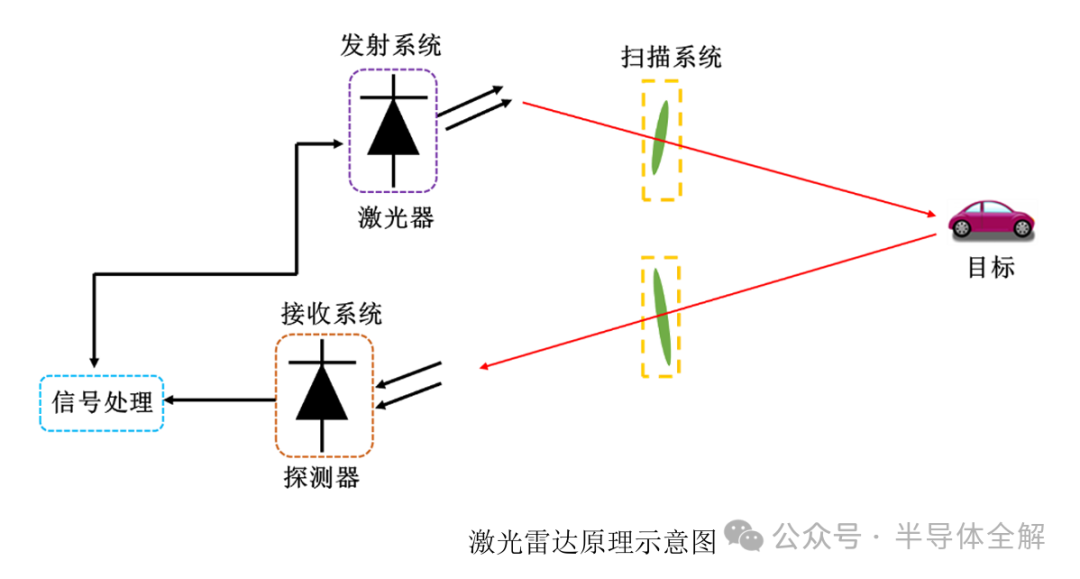
The detection principle of LiDAR is similar to that of radar, differing in that it uses laser as the detection medium instead of microwaves. Due to the small divergence angle of lasers, LiDAR has a higher angular resolution.
The principle of LiDAR is as follows: the laser emitted by the transmission system is reflected off the object’s surface and is received by the receiving system. After being processed by the data processing module, precise object location information is obtained.
3. Main Classifications of LiDAR
LiDAR can be classified into two types based on differences in detection principles: incoherent detection LiDAR and coherent detection LiDAR. The following will specifically introduce the principles and representative schemes of these two detection methods.
LiDAR based on incoherent detection principles is mainly ToF (Time of Flight) LiDAR, which typically uses pulse light sources with wavelengths of 905 nm or 940 nm. As shown in the figure below:
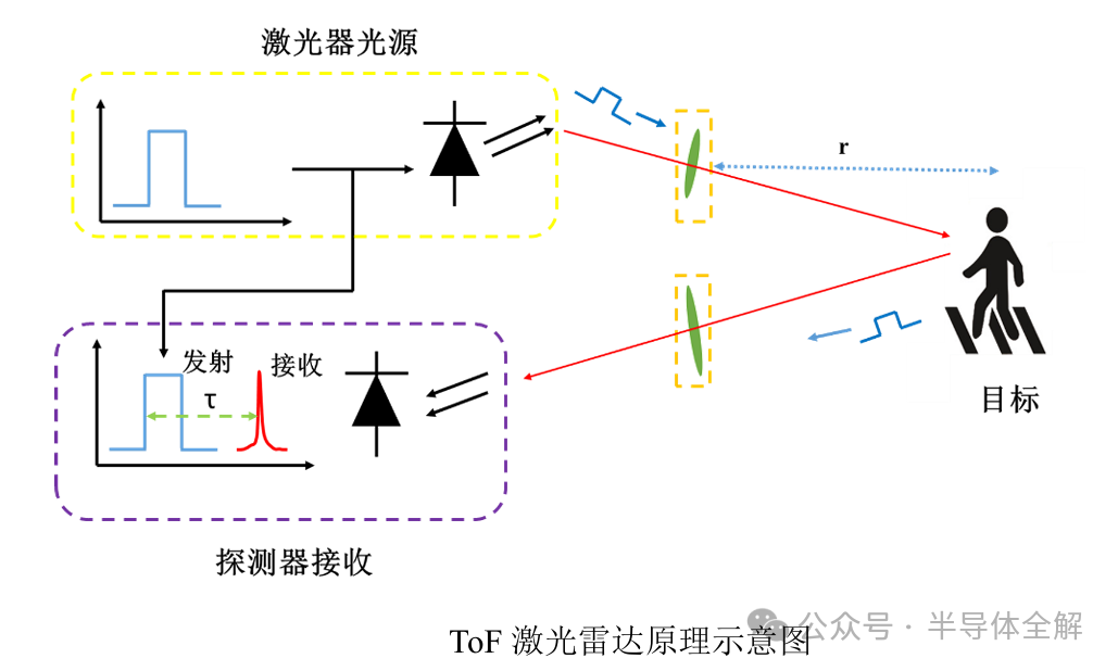
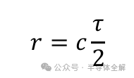
The principle of ToF LiDAR is as follows: a pulse of light is emitted by the laser, reflected off the object’s surface, and received by a detector at the receiving end. By extracting the time difference τ from emission to reception, the distance r to the object can be calculated as:
Where c is the speed of light, typically taken as 3×10^8 m/s in air.
LiDAR based on coherent detection principles is mainly FMCW (Frequency Modulated Continuous Wave) LiDAR, which uses optical heterodyne coherent detection to obtain information about objects, with the laser source typically having a wavelength of 1550 nm. Unlike the light source used in ToF LiDAR, this scheme uses a laser with a continuously varying frequency. The figure below shows a schematic of FMCW LiDAR measuring a stationary object with a triangular wave frequency sweep format.
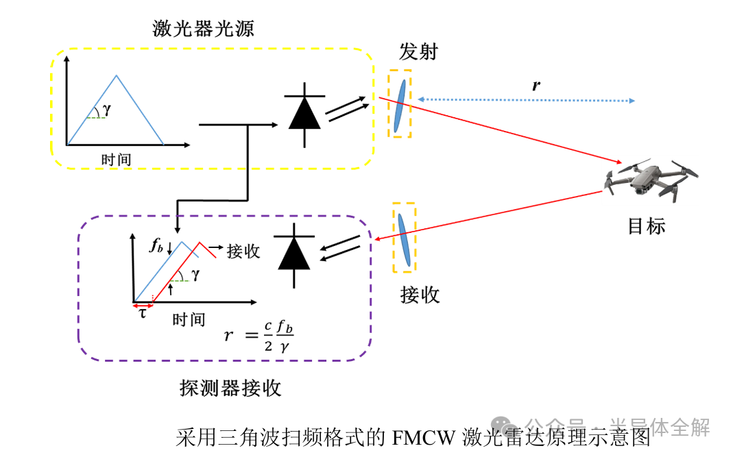
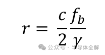
The principle of FMCW LiDAR detection is: the laser with a frequency that varies linearly over time is split into two paths, one as the detection light and the other as the local oscillator light. The detection light reflects off the object’s surface and, upon reception, mixes coherently with the local oscillator light to produce a beat frequency signal. The relationship between the distance r to the object and the frequency fb of the beat frequency signal light is as follows:
Where c is the speed of light, and γ is the slope of the laser frequency variation over time.
4. Comparison of FMCW LiDAR and ToF LiDAR
As the next generation of sensors expected to be mounted on vehicles, FMCW LiDAR has the following advantages over ToF LiDAR:
First, the light source of FMCW LiDAR is a continuously varying frequency laser, using optical heterodyne coherent detection. The local oscillator light amplifies the detection light, and compared to ToF LiDAR, FMCW LiDAR has lower requirements for light source power; the continuous wave operating mode has a smaller average power compared to the pulsed mode. In addition, FMCW LiDAR has higher sensitivity and resolution.
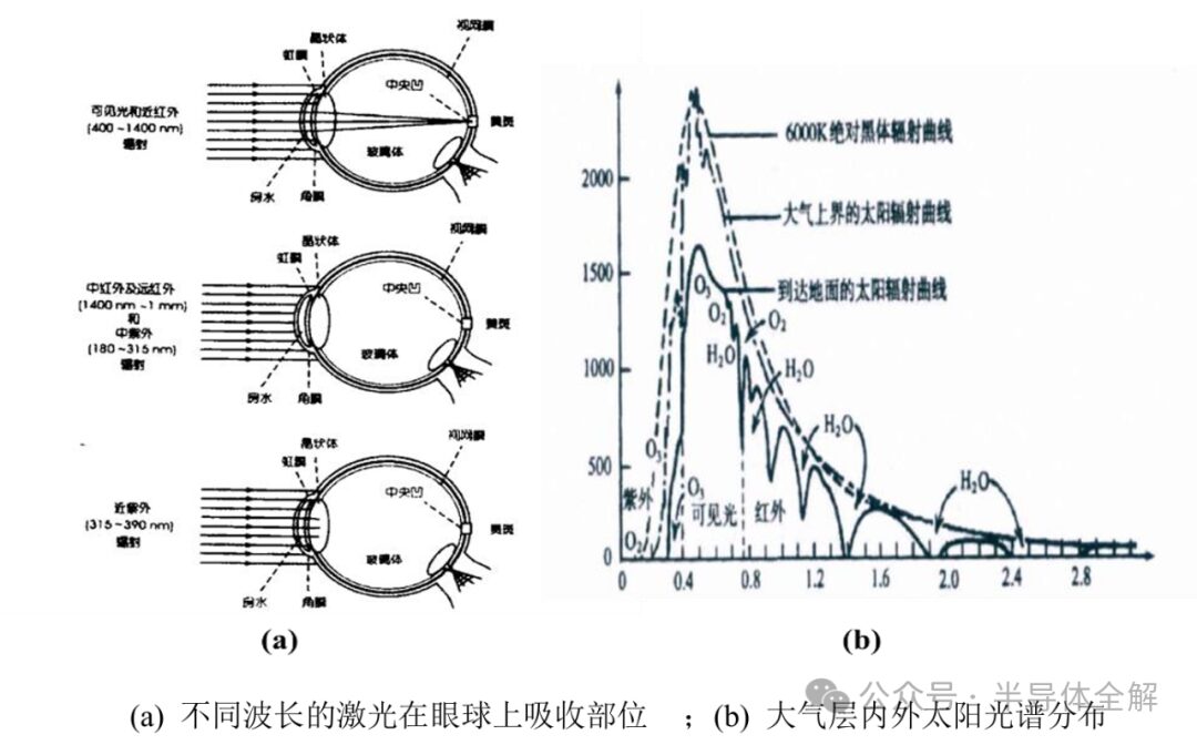
Second, ToF LiDAR mostly uses high-energy pulsed lasers with wavelengths of 905 nm or 940 nm as the light source, as shown in the figure (a), while FMCW LiDAR uses 1550 nm lasers that are safer for human eyes, meaning that the emission power and detection distance of FMCW LiDAR are not overly restricted by safety concerns. Meanwhile, as shown in the figure (b), the 1550 nm laser is far from the visible spectrum and is less affected by ambient light. Furthermore, the 1550 nm laser has strong penetration capability in air and is not easily scattered or absorbed.
Third, FMCW LiDAR using a triangular wave frequency sweep format can simultaneously extract the frequency difference introduced by distance and the Doppler frequency shift caused by relative speed in a single measurement, allowing it to obtain both distance and speed information of the object.
In contrast, ToF LiDAR can only obtain distance information in a single measurement.
In summary, compared to ToF LiDAR, FMCW LiDAR has advantages such as high sensitivity and high resolution, low energy consumption, strong anti-interference capability, minimal harm to human eyes, and the ability to simultaneously obtain distance and speed information in a single measurement, garnering increasing attention.
5. Frequency Sweep Formats of FMCW LiDAR Light Source
As shown in the figure below, there are three commonly used frequency sweep formats for FMCW LiDAR light sources: sawtooth wave, triangular wave, and sine wave.
These three sweep formats generate beat frequency signals through optical heterodyne coherent detection, and by extracting the frequency of the beat frequency signal, the distance information of the object is ultimately calculated.
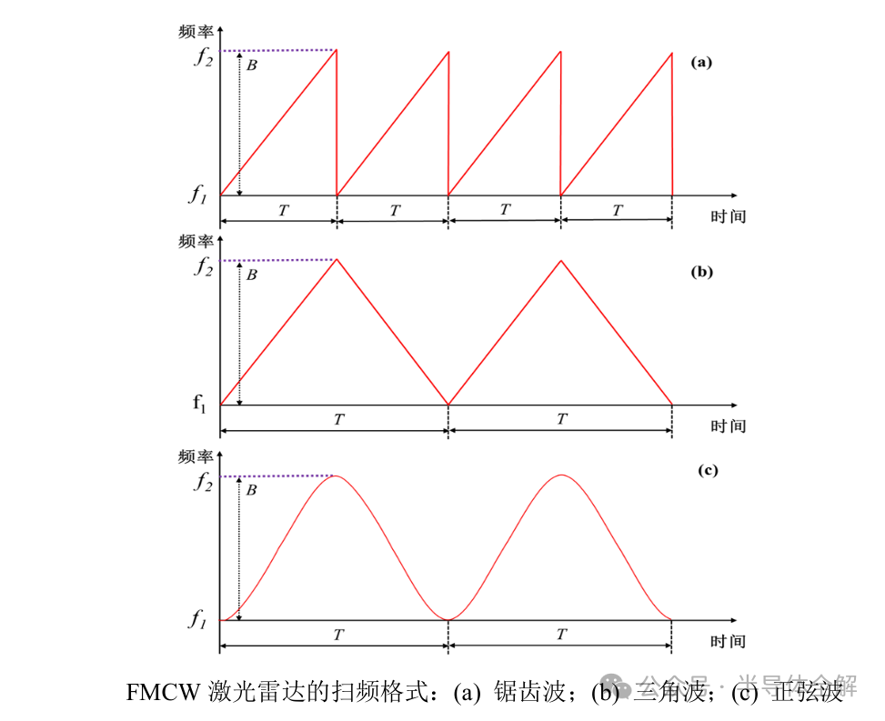
1. FMCW LiDAR using a sawtooth wave frequency sweep format obtains a single frequency beat frequency signal through coherent detection, which is easy to process. However, when the object is in motion, the Doppler frequency shift introduces measurement error, so this sweep format is only suitable for measuring stationary objects.
2. FMCW LiDAR using a triangular wave frequency sweep format obtains the beat frequency signals for the upper and lower slopes through coherent detection, making data processing more complex. During measurement, the frequencies of the beat frequency signals from the upper and lower slopes are extracted separately, and their sum can eliminate the influence of Doppler frequency shift on the distance measurement, while their difference provides the object’s speed information. Therefore, FMCW LiDAR using a triangular wave frequency sweep format can simultaneously obtain both distance and speed information in a single measurement.
3. FMCW LiDAR using a sine wave frequency sweep format easily obtains linear frequency scanning, but this sweep format produces unstable frequencies of the beat frequency signal and has lower measurement accuracy, so this sweep format is generally not used for measurement.
The reproduced content only represents the author’s viewpoint
It does not represent the position of the Semiconductor Institute of the Chinese Academy of Sciences
Responsible editor: Mu Xin
1. The Semiconductor Institute has made progress in the research of bionic covering-type neuron models and learning methods
2. The Semiconductor Institute has made important progress in inverted structure perovskite solar cells
3. Why is copper used as the interconnect metal in chips?
4. What exactly is 7nm in chips?
5. Silicon-based integrated photonic quantum chip technology
6. How abnormal is the quantum anomalous Hall effect? It may bring about the next revolution in information technology!