1. Single Channel Sampling Reference Materials:
“Practical Guide to STM32 Library Development” by Liu Huoliang and Yang Sen
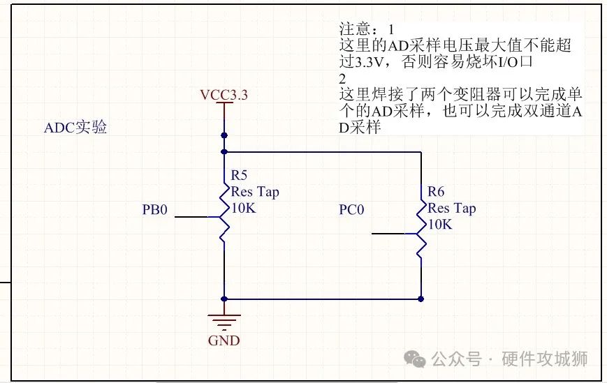
We will skip the theoretical aspects as they are well explained in the book above, let’s directly look at the hardware circuit diagram.
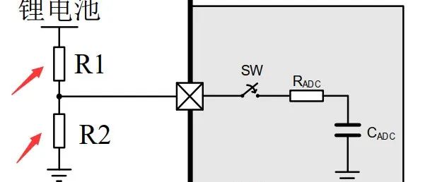
Here, we are using a 3362 potentiometer (10K), measuring the voltage across PB0 and GND. This circuit design is relatively simple and easy to understand, but it has certain drawbacks. Below is the hardware circuit diagram from the “Practical Guide to STM32 Library Development” 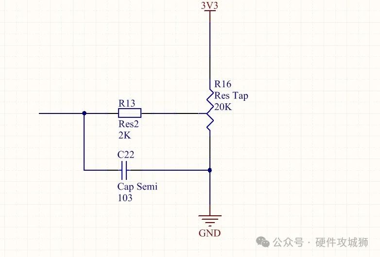 If designing a circuit diagram, you can refer to this approach.
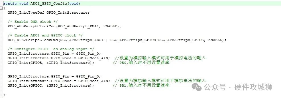
1. When initializing pins, pay attention to
If designing a circuit diagram, you can refer to this approach.
1. When initializing pins, pay attention to 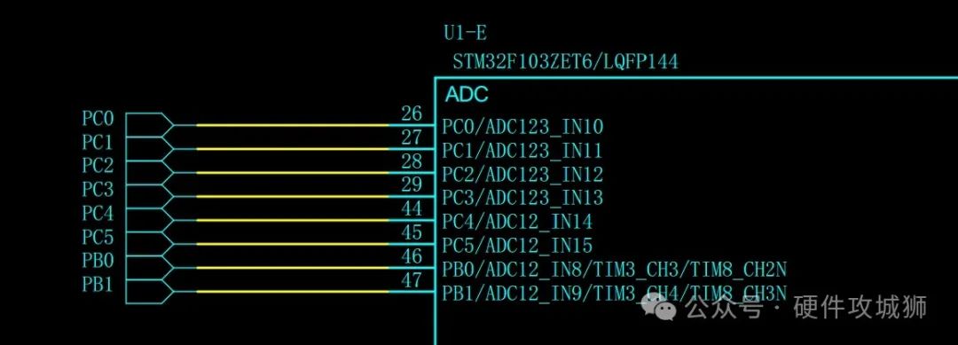 Each ADC channel corresponds to a GPIO pin. For example, ADC123_IN10 indicates that this pin (PC0) can be configured as channel 10 of ADC1, ADC2, or ADC3. This is very important as it relates to the function calls during ADC initialization.
For instance, when we enable ADC, the function we call is
Each ADC channel corresponds to a GPIO pin. For example, ADC123_IN10 indicates that this pin (PC0) can be configured as channel 10 of ADC1, ADC2, or ADC3. This is very important as it relates to the function calls during ADC initialization.
For instance, when we enable ADC, the function we call is
ADC_Cmd();
If we are using ADC1, then the function should be written as
ADC_Cmd(ADC1,ENABLE);
Correspondingly, if it’s ADC2, the function should be
ADC_Cmd(ADC2,ENABLE);
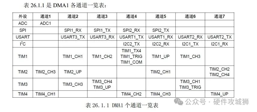
Additionally, it should be noted that we are using DMA with our ADC, so if you are using ADC1, the corresponding DMA should be DMA1 channel 1.
If using ADC2 or ADC3, you’ll need to check the manual for the corresponding DMA channel.
In the uploaded program, you can see the following statement during DMA initialization
DMA_Init(DMA1_Channel1);
This initializes DMA1 channel 1.
DMA_Cmd(DMA1_Channel1,ENABLE);
In summary, different IO ports correspond to different ADC and DMA configurations.
In single-channel ADC sampling, paying attention to the above point is sufficient, but for multi-channel sampling, other aspects need attention.
2. Multi-channel Sampling
Again, refer to the circuit diagram above.
Here, we assume using PB0 and PC0 ports to collect voltage.
STM32 has three ADCs, each corresponding to 16 channels; here we only use two channels for illustration.
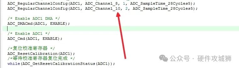
In the program, PB0 is set as channel 8 of ADC1, and PC0 is set as channel 10 of ADC1.
1. Pin configuration has already been mentioned.
2. Configuration of ADC mode.
ADC mode configuration is mainly completed by initializing the members of the ADC_InitTypeDef structure.
ADC_InitTypeDef ADC_InitStructure;
ADC_InitStructure.ADC_ScanConvMode=ENABLE;
This member of the structure is mainly used to set the ADC’s scan mode. Since we are using channels 8 and 10, we must allow the ADC to scan the channels.
ADC_InitStructure.ADC_NbrOfChannel=2;
This member indicates the number of channels to be converted. Since we are using channels 8 and 10, this value must be 2.
ADC_RegularChannelConfig();
This is a very important function 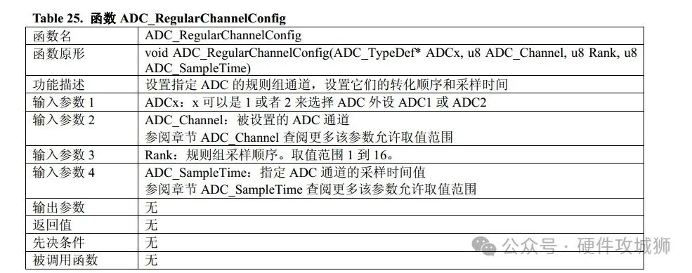 This is an excerpt from the “STM32 Library Function Usage Manual”. For specific parameters, please refer to that manual.
Now let’s look at how this function is used in the program.
The third parameter of the function is used to set the sampling order. According to our program, we set ADC1 channel 8 to sample first, followed by ADC1 channel 10.
At this point, the multi-channel ADC sampling program is almost complete. You can refer to the program I uploaded later for specific DMA usage.
Disclaimer: This account maintains neutrality regarding all original and reprinted articles’ statements and views. The articles are only for readers’ learning and communication. Copyright for articles, images, etc., belongs to the original authors. If there is any infringement, please contact for deletion.
This is an excerpt from the “STM32 Library Function Usage Manual”. For specific parameters, please refer to that manual.
Now let’s look at how this function is used in the program.
The third parameter of the function is used to set the sampling order. According to our program, we set ADC1 channel 8 to sample first, followed by ADC1 channel 10.
At this point, the multi-channel ADC sampling program is almost complete. You can refer to the program I uploaded later for specific DMA usage.
Disclaimer: This account maintains neutrality regarding all original and reprinted articles’ statements and views. The articles are only for readers’ learning and communication. Copyright for articles, images, etc., belongs to the original authors. If there is any infringement, please contact for deletion.
Using ADC to Accurately Measure Resistance Values
Is the ADC Collection Really Designed Correctly?
👇 Focus on Sharing Electronic Hardware Knowledge 👇
Support quality content, please “share, like, and follow” 👇