
This article can serve as a basic guide for connecting RS-485 networks. The RS-485 specification (officially known as TIA/EIA-485-A) does not specifically dictate how to connect RS-485 networks. Nevertheless, the specification does provide some guidelines. These guidelines and good engineering practices form the basis of this article. However, the recommendations presented in this article do not cover all the different ways to design a network.
RS-485 transmits digital information between multiple locations. The data rate can reach up to 10 Mbps, and sometimes even higher. The RS-485 design is primarily intended for transmitting information over long distances, fully capable of meeting distances of up to 1000 meters. The successful transmission distance and data rate of RS-485 largely depend on the wiring method of the system.
Wiring
RS-485 is designed as a balanced system. Simply put, it uses two wires to transmit signals without a ground.
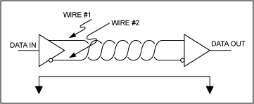
Figure 1. A balanced system uses two wires to transmit data without a ground.
The system is termed balanced because ideally the signal on one wire is strictly opposite to the signal on the other wire. That is, if one wire sends a high level, the other wire will send a low level, and vice versa, see Figure 2.
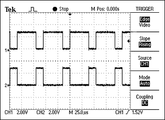
Figure 2. The signals on the two wires of a balanced system are strictly opposite.
Although RS-485 can successfully transmit using various types of media, the wiring method commonly known as “twisted pair” should be used.
What is a Twisted Pair? Why Use Twisted Pairs?
As the name suggests, a twisted pair consists of a pair of equal-length wires twisted together. Transceivers compatible with RS-485 used with twisted pairs can reduce the two main sources of failure in designing high-speed long-distance networks: radiated EMI and received EMI.
Radiated EMI
As shown in Figure 3, high-frequency components are generated when information is sent using fast-changing edges. Since RS-485 can transmit at high data rates, fast-changing edges are essential.
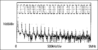
Figure 3. 125kHz square wave and its FFT plot.
The inevitable high-frequency components in fast-changing edges couple with long connecting wires, producing radiated EMI. The balanced system of twisted pairs makes the system an inefficient radiator, reducing this effect. The principle is simple: since the signals on the transmission lines are equal and opposite in polarity, the signals radiated on each line are also equal and opposite in polarity. This results in a canceling effect, meaning there is no net radiated EMI. However, this outcome is based on one premise: the lengths of the connecting wires are strictly equal and their positions are strictly the same. Since two wires cannot simultaneously be in the same position, they should be kept as close as possible to each other. Twisting the two wires together limits the distance between them, helping to cancel out residual EMI.
Received EMI
Received EMI is essentially the same issue as radiated EMI but in the opposite direction. The cables used in RS-485 systems also act as antennas that receive harmful signals. These harmful signals can distort useful signals and, if severe enough, cause data errors. For the same reasons that twisted pairs help prevent radiated EMI, twisted pairs also help reduce the impact of received EMI. Because the two wires are close together and twisted, the noise received on one wire tends to be similar to the noise received on the other wire. This type of noise is known as “common-mode noise.” Since RS-485 receivers are designed to detect signals that are opposite in polarity to each other, they easily suppress common-mode noise.
Characteristic Impedance of Twisted Pairs
The “characteristic impedance” of twisted pairs is generally provided by the manufacturer based on the cable’s geometry and the insulation materials used. The RS-485 specification recommends but does not specifically mandate that the characteristic impedance should be 120Ω. This impedance is recommended as it is necessary for calculating the worst-case operating conditions load and the common-mode voltage range in the RS-485 specification. The specification does not specifically dictate this impedance, possibly for flexibility. If for some reason a 120Ω cable cannot be used, it is recommended to recalculate the worst-case operating conditions load (the number of transmitters and receivers that can be used) and the worst-case common-mode voltage range to ensure that the designed system can function properly. The industry standard TSB89 “ATIA-EIA-485-A Application Guidelines” includes a chapter dedicated to these calculations.
Number of Twisted Pair Per Transmitter
After understanding the required type of transmission line, the reader may ask: How many pairs of twisted pairs can a single transmitter drive? The simple answer is: only one pair.Although a transmitter may drive multiple twisted pair pairs under certain environmental conditions, this is not compliant with the specification.
Termination Resistors
Due to the involvement of high frequencies and distances, transmission line effects must be closely monitored. However, a detailed discussion of transmission line effects and proper termination techniques is beyond the scope of this application note. Therefore, this article briefly discusses the simplest form of termination resistors related to RS-485.
Termination resistors are installed at the end of the cable (Figure 4). The value of the termination resistor ideally matches the characteristic impedance of the cable.
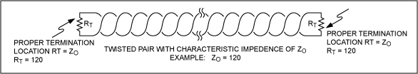
Figure 4. The termination resistor value should match the characteristic impedance of the twisted pair and should be installed at the far end of the cable.
If the value of the termination resistor differs from the characteristic resistance value of the connecting wire, reflections will occur as the signal transmits through the cable. This process is described by the formula (Rt – Zo)/(Zo + Rt), where Zo is the cable impedance and Rt is the termination resistor value. Although cable and resistor tolerances will cause some unavoidable reflections, a sufficiently large mismatch will cause larger reflections that can lead to data errors, see Figure 5.
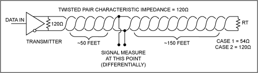
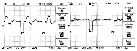
Figure 5. Using the circuit shown above, the waveform on the left is obtained through MAX3485, which drives a 120Ω twisted pair cable with a termination resistor of 54Ω; the waveform on the right is obtained with a correctly terminated cable using a 120Ω resistor.
After understanding reflections, it is crucial to match the termination resistor with the characteristic impedance as closely as possible. The position of the termination resistor is also very important. The termination resistor should be installed at the far end of the cable.
Additionally, as a general rule, termination resistors should be installed at both ends of the cable. While it is critical for most system designs to correctly install termination resistors at both ends, it can be argued that in certain special cases, only one termination resistor is needed. When there is only a single transmitter in the system and the transmitter is located at the far end of the cable, in this case, since the signal is always sent from the end of the cable where the transmitter is located, there is no need to install a termination resistor at that end.
Maximum Number of Transmitters and Receivers on the Network
The simplest RS-485 network consists of one transmitter and one receiver, although this configuration is useful in many applications, RS-485 allows multiple receivers and transmitters to be connected to a pair of twisted pairs, offering greater flexibility. The maximum number of transmitters and receivers allowed depends on the load each device forms on the system. Ideally, the impedance of all receivers and stopped transmitters is infinite, which does not overload the system. However, this is not the case in practical applications. Each receiver connected to the network and all stopped transmitters will increase the load.
To help RS-485 network designers determine how many devices can be added to the system, a hypothetical unit called “unit load” is created. All devices connected to the RS-485 network should be characterized as multiples or fractions of unit load. Two examples are MAX3485 (specified as 1 unit load) and MAX487 (specified as 1/4 unit load). Assuming the characteristic impedance of the cable is 120Ω and properly terminated, the maximum number of unit loads allowed on a pair of twisted pairs is 32. In the above example, this means that up to 32 MAX3485s or up to 128 MAX487s can be connected on a single network.
Fail-Safe Bias Resistors
When the input is between -200mV and +200mV, the receiver output is “undefined.” There are four common fault conditions that can cause the receiver output to be undefined, leading to data errors:
-
All transmitters in the system are turned off
-
The receiver is not connected to the cable
-
The cable is open
-
The cable is shorted
Using fail-safe biasing ensures that the receiver output is in a defined state when any of the above conditions occur. Fail-safe biasing includes pull-up resistors on the non-inverting line and pull-down resistors on the inverting line. When biased correctly, if any fault condition occurs, the receiver will output a valid high level. These fail-safe bias resistors should be installed at the receiver end of the transmission line.
ADI’s MAX13080 and MAX3535 families of transceivers do not require fail-safe bias resistors because the devices already integrate true fail-safe features. In true fail-safe functionality, the receiver threshold range is -50mV to -200mV, so fail-safe bias resistors are unnecessary while fully complying with RS-485 standards. These devices ensure that a logic “high” output is produced when the receiver input is at 0V. Moreover, this design guarantees that the receiver output state is defined under open or short circuit conditions.
Correct Network Examples
After understanding the above information, we can design some RS-485 networks. Here are a few examples.
One Transmitter, One Receiver
The simplest network consists of one transmitter and one receiver (Figure 6). In this example, the termination resistor is located at the transmitter end of the cable. Although it is not necessary in this example, designing for two termination resistors is good practice. This allows the transmitter to move to other positions beyond the far end and permits the addition of more transmitters to the network when necessary.
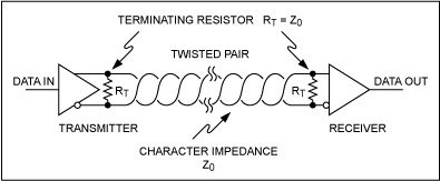
Figure 6. RS-485 network with one transmitter and one receiver.
One Transmitter, Multiple Receivers
Figure 7 shows a network with one transmitter and multiple receivers. In this example, it is very important to keep the distance of the twisted pair to the receivers as short as possible.
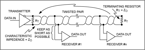
Figure 7. RS-485 network with one transmitter and multiple receivers.
Two Transceivers
Figure 8 shows a network with two transceivers.
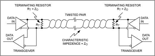
Figure 8. RS-485 network with two transceivers.
Multiple Transceivers
Figure 9 shows a network with multiple transceivers. As with the one transmitter, multiple receivers network shown in Figure 7, it is crucial to keep the distance of the twisted pair to the receivers as short as possible.
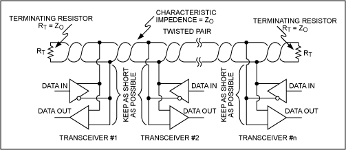
Figure 9. RS-485 network with multiple transceivers.
Incorrect Network Examples
Below are examples of incorrectly configured systems. Each example shows waveforms obtained from improperly designed networks compared to the waveforms obtained from correctly configured systems. The waveforms are measured in differential form (A-B) from points A and B.
Unterminated Network
In this example, the termination resistor is not installed at the end of the twisted pair. When the signal transmits along the connecting wire, it encounters an open circuit at the end of the cable. This creates an impedance mismatch, resulting in emissions. In the open circuit case (shown below), all energy is reflected back to the source end, causing severe distortion of the waveform.
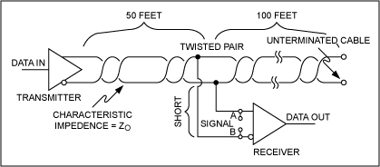
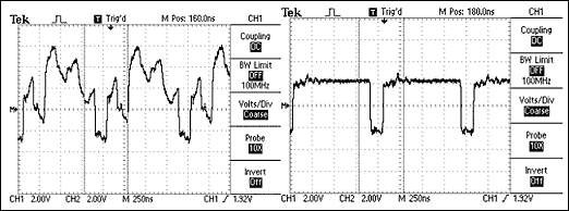
Figure 10. Untterminated RS-485 network (top image) and its generated waveform (left image), as well as the waveform obtained from a correctly terminated network (right image).
Incorrect Termination Position
This example has a termination resistor installed, but it is not placed at the far end of the cable. When the signal transmits along the connecting wire, it encounters two instances of impedance mismatch. The first occurs at the termination resistor. Even if the resistor matches the characteristic impedance of the cable, there is still cable after the resistor. The subsequent cable causes another impedance mismatch, leading to reflections. The second mismatch occurs at the end of the unterminated cable, causing further reflections.
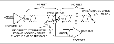
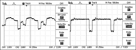
Figure 11. RS-485 network with incorrect termination position (top image) and its generated waveform (left image), as well as the waveform obtained from a correctly terminated network (right image).
Multiple Cables
The layout shown in Figure 12 has multiple issues. The RS-485 driver is designed to drive a single pair of properly terminated twisted pairs. In this case, the transmitter drives four pairs of parallel twisted pairs. This means that the required minimum logic levels cannot be guaranteed. Besides the large load, impedance mismatches exist at the junctions of multiple cables. Impedance mismatches mean reflections, which in turn cause signal distortion.
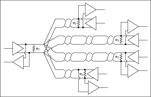
Figure 12. Incorrect use of multiple pairs of twisted pairs in an RS-485 network.
Long Branches
In Figure 13, the cable is correctly terminated, and the transmitter drives only one pair of twisted pairs. However, the connection points (branches) of the receivers are too long. Long branches cause significant impedance mismatches, leading to reflections. All branches should be kept as short as possible.
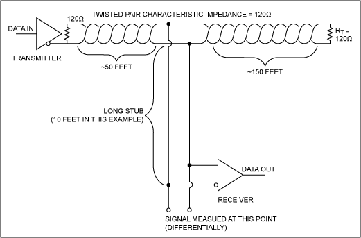
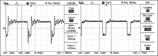
Figure 13. RS-485 network with a branch length of 10 feet (top image) and its generated waveform (left image), as well as the waveform obtained from a short branch (right image).