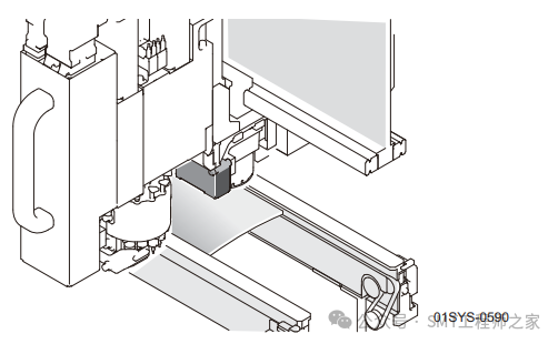
The PCB height detection function of the NXT pick and place machine is a feature that measures the warpage of the circuit board transported onto the transport track.
For circuit boards with warpage, in addition to ensuring stable component placement, if the warpage exceeds the tolerance value, please avoid production in advance to prevent the occurrence of defective circuit boards.
1. Using the PCB Height Detection Function
1. Please press the START button on the operation panel to begin production.
2. If the PCB height reference point reading fails, or if a PCB exceeding the warpage tolerance is detected, the machine will stop abnormally.
3. Please resolve the abnormality and continue production.
2. Abnormalities During Use
The following describes the abnormalities that may occur when using the PCB height detection function and their countermeasures.
1. PCB Height Reference Point Reading Abnormality
If the PCB height reference point reading fails and cannot be read after repeated attempts, the machine will release the PCB and display an abnormality guide on the operation screen.
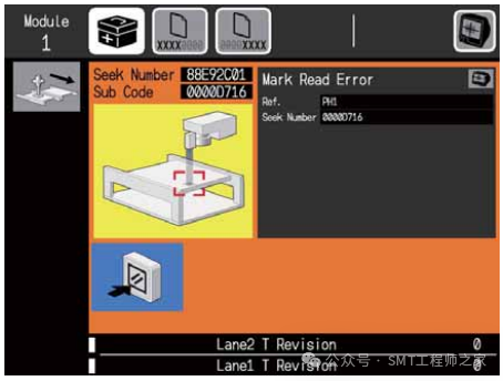
a. Please press the camera button to confirm the image being captured.b. Please confirm the position of the PCB height reference point using SeeKNumber and the image.c. Please press the READYON button to clear the abnormality screen.d. If necessary, please use MEdit to edit the position of the PCB height reference point. After editing, please reflect this to the Job.
2. PCB Warpage Tolerance Range Abnormality
If warpage exceeding the tolerance value is detected, the machine will release the PCB and display an abnormality guide on the operation screen.
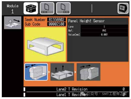
a. Please press the module pull-out button and pull out the module.b. Remove the PCB.c. Confirm the degree of warpage of the PCB. If the warpage can be corrected by supporting pins, please return the PCB to the transport track.d. Please insert the module.
3. Outputting PCB Height Measurement Results
Through remote operation of auxiliary software, the PCB height measurement results can be output in text file format.
1. How to Output Data
Transfer the production Job to the machine and perform the following operations.
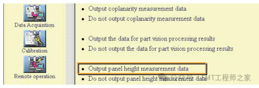
1) In the machine setting screen of the auxiliary software, please select the target module.2) In the remote operation menu, please execute the [Outputpanelheightmeasurementdata] command.
Note: Executing the command will clear all previous measurement results. If data is needed, please obtain the file in advance before executing the command.
3) Please press the START button on the operation panel. Start production, and the PCB height measurement result data will be automatically output.
(Note: The measurement results for each track are saved in text file format in the base’s register.)
Additionally, even if the above operations are performed, data output will not occur when the machine is in the following states.
· When the main switch is set to ON· When the output file size for the 11 tracks reaches 1MB· When transmitting a different Job during dual-track production· When a complete Job is transmitted
2. How to Retrieve Output Data
Please follow the steps below to obtain the PCB height measurement result data.
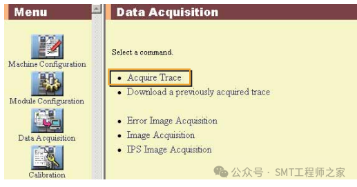
1) In the machine setting screen of the auxiliary software, please select the target module.2) In the machine information retrieval menu, please execute the [AcquireTrace] command.
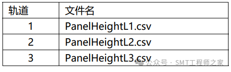
3) Save the file in any folder.(Note: After executing the trace acquisition, the files in the base’s register will be deleted. Since the files cannot be recovered, please manage the saved files carefully to avoid loss.)4) The saved file is compressed in zip format. Please use a decompression tool to extract the file. The file name of the PCB height measurement result is as follows.
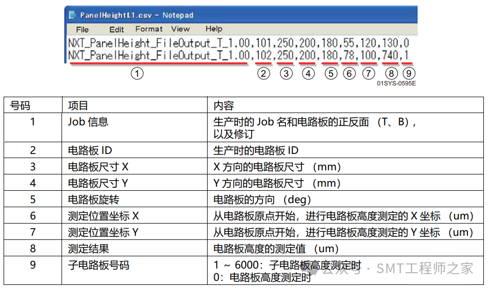
3. How to View the Retrieved Data
Please use a text editor such as Notepad to open the retrieved text file. The following explains the various items in the file.