Fanuc Robot 3D Vision System Video
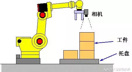
iRVision 2.5D Vision Stacking
The vision stacking program estimates the height of the target by observing changes in the target’s proportion within the camera’s field of view and guides the robot’s motion to compensate for the target’s offset, which includes not only the X-axis, Y-axis, and rotation in the X-Y plane (R), but also the Z-axis.
Using iRVision 2.5D allows the robot to pick up stacked targets using only a standard 2D camera.
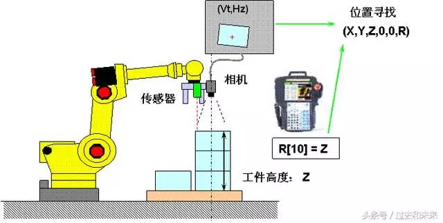
iRVision Vision Stacking Program_1 (Extracting Z-axis Offset from Register R)
This function finds the 2D position of the target and the specified register value through visual calculation, guiding the robot’s motion to compensate for the target’s offset, which includes not only the X-axis, Y-axis, and rotation in the X-Y plane (R), but also the Z-axis.
Register R is used to store the known Z-axis height of the target or the Z-axis height information detected by a distance sensor.
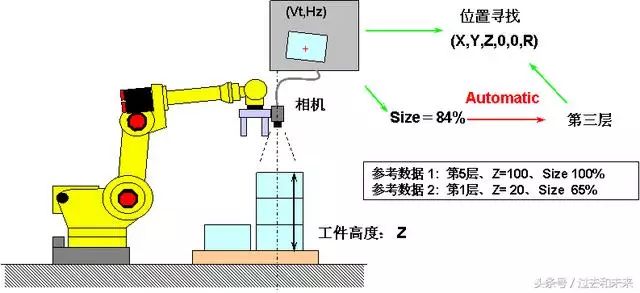
iRVision Vision Stacking Program_2 (Extracting Z-axis Offset from Stacking Layers)
This function calculates the position of the target by combining visual detection results with the number of layers of the target (target height) determined by the target’s proportion. The number of layers is automatically determined based on reference proportions and height data, thus allowing for the calculation of the target’s specific position even in the presence of slight proportional errors during visual detection.
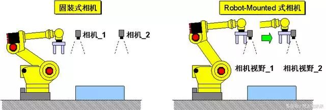
iRVision 2DV Multiple Field Function
The 2D multiple field program provides the ability to locate large targets using several fixed cameras, which is also effective when detecting through a robot-mounted camera.
iRVision 3DL Multiple Field Function
The 3D multiple field program provides the ability to locate large targets using several fixed 3D cameras, which is also effective when detecting through a robot-mounted camera.
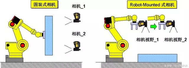
iRVision Floating Coordinate System Function (Floating Frame)
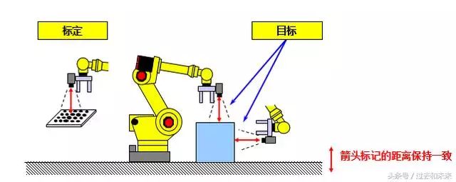
The calibration of the robot-mounted camera can be used for the iRVision program at any position and orientation as shown in the figure below. The motion compensation in 2D is associated with the actual position of the camera. Calibration can be performed at any position, reducing teaching workload.
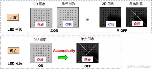
iRVision 3DL LED Light Source Control
This function supports synchronizing the control of the LED light source ON/OFF during the capture of 2D images and laser illumination images in the 3DL vision program. This functionality can achieve an appropriate external lighting environment, enhancing the overall capability of the vision system.
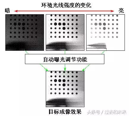
iRVision Automatic Exposure Function
According to changes in the intensity of surrounding ambient light, iRVision will automatically adjust the exposure time to achieve imaging results similar to well-taught images, allowing for all-weather operation.
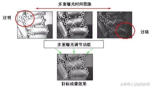
iRVision Multiple Exposure Function
By imaging with multiple different exposure times, select an image that closely resembles the taught effect to achieve a broad and dynamic exposure range and imaging effect. This function performs well when there are significant changes in ambient light.
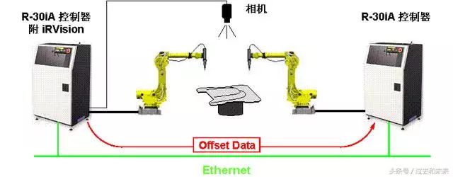
iRVision Ring Network Function (Robot Ring)
This function allows robots not equipped with the iRVision vision system to call the offset detection data from robots equipped with the iRVision vision system via the network.
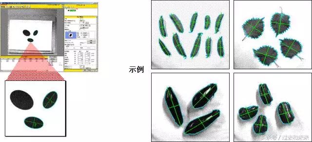
iRVision Blob Detection Function (Blob Locator Tool)
Detects the position of binary (black and white) targets within the imaging range that have similar characteristics (such as perimeter, curvature, etc.) to the taught model. When used in conjunction with the Conditional Execution Tool, it can be applied to various scenarios such as target arrangement and quality inspection.
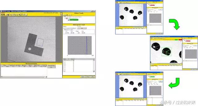
iRVision Grayscale Detection Function (Histogram Tool)
Detects the light intensity (imaging grayscale) within a specified area and calculates various characteristics such as average, maximum, and minimum values. When used in conjunction with the Conditional Execution Tool, it can correspond to target arrangement and target presence detection in various scenarios.
This function is equivalent to the Associate Tool in V-500iA/2DV.
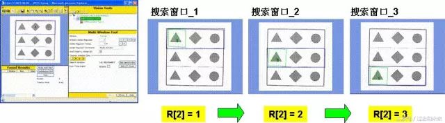
iRVision Multi-Window Detection Function (Multi-Window Tool)
Switches corresponding preset search windows based on changes in the value of register R within the robot controller.
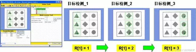
iRVision Multi-Target Detection Function (Multi-Locator Tool)
Switches corresponding preset target vision programs based on changes in the value of register R within the robot controller.
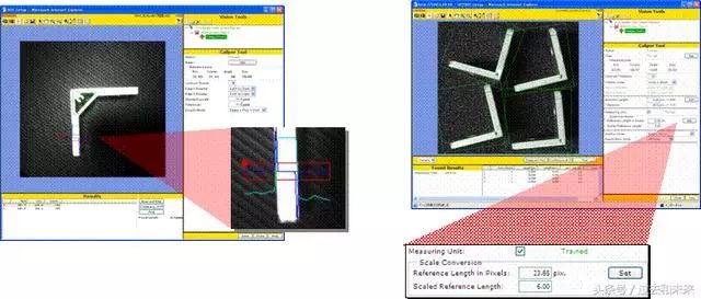
iRVision Length Measurement Function (Caliper Tool)
Detects the edges of the target within a specified area and measures the length between the two edges (unit: pixels), which can be converted to mm by multiplying with a conversion factor. This can correspond to target arrangement and quality inspection applications.
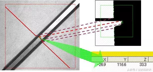
iRVision Cross Section Detection Function (Cross Section)
Detects the local 3D characteristics of the target, displaying the cross-sectional shape of the target along the laser projection path. This is particularly effective in 3D vision programs where accurate positioning cannot be achieved due to a lack of effective feature quantities in 2D imaging.
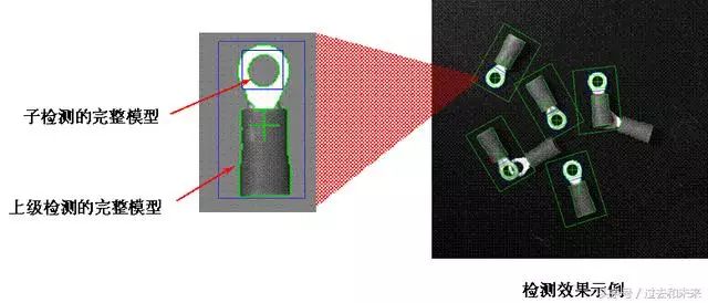
iRVision Child Detection Function (Child Tool)
Allows for the addition of a child target detection (GPM locator tool) under a parent target detection (GPM locator tool) to form a secondary detection directory. The child detection will dynamically determine based on the results of the parent detection. When used in conjunction with the Conditional Execution Tool, it can correspond to target arrangement and target presence detection in various scenarios.
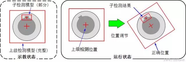
iRVision Position Adjustment Function (Position Adjust Tool)
Based on the results of child detection, adjusts the positioning of the parent detection to correspond to significant features on the target surface (such as holes, key slots), obtaining more precise offset and rotation data. This is particularly effective for applications that cannot be directionally positioned using the entire taught model. Multiple subordinate detections can be used to analyze various local characteristics of the target for a superior detection.
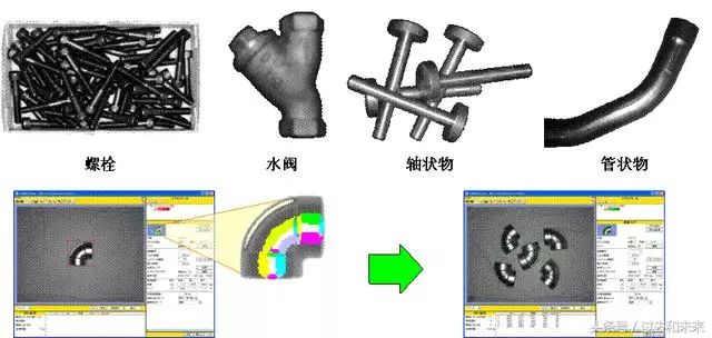
iRVision Curved Surface Matching Function (Curved Surface Matching Tool)
Detects the offset and rotation of curved surface targets by the step-like light intensity distribution (bright or dark, displayed in different colors within the model) on the target surface. It may recognize full circular objects.
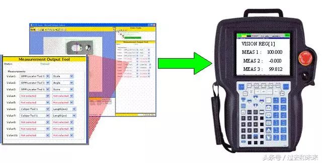
iRVision Measurement Output Function (Measurement Output Tool)
Outputs measurement values (such as “Score/分值”, “Size/比例” in the Locator tool, “Length/长度” in the Caliper tool) to the vision register VR. This data can be copied to the robot data register R and freely called in the TP program.
iRVision Vision Shift Function
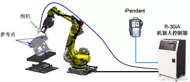
Adjusts the robot TP program to correspond to the actual workpiece position through the vision program, requiring only the addition of a camera at the end of the robot’s gripper to execute this function. The positional data of three arbitrary reference points on the fixed workpiece will be automatically detected and compensation data calculated. Using this function after offline programming or relocation of the robot system can greatly reduce the time needed for re-teaching the robot.
iRVision Vision Mastering Function
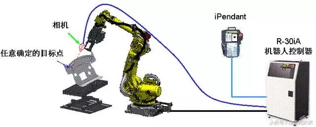
Compensates the zero position data of the robot’s J2~J5 axes through the vision program, requiring only the addition of a camera at the end of the robot’s gripper to execute this function. The robot changes to different postures, and the relative position data between the camera and the determined target point will be automatically detected and compensation data calculated. This function can be applied to improve the accuracy of robot TCP teaching, vision shift offline programming, and other vision applications.
iRVision Vision Frame Set Function_1
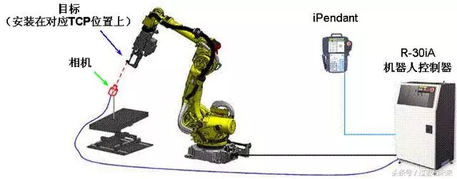
Sets the robot TCP through the vision program, requiring only the addition of a camera at the corresponding position of the robot’s gripper TCP to execute this function. The robot changes to different postures, and the relative position data between the camera and the target point under the corresponding user coordinate system will be automatically detected and calculated for the robot’s corresponding TCP. This function can enhance the speed and accuracy of TCP teaching.
iRVision Vision Frame Set Function_2
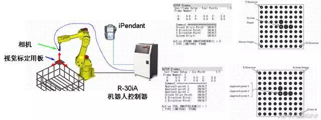
Another function for setting the coordinate system: sets a user coordinate system equivalent to the vision calibration board through vision. The user coordinate system UF is set at the origin of the vision calibration board (four-point method) or when the vision calibration board is mounted at the end of the robot’s gripper, the tool coordinate system UT is set at the origin of the vision calibration board (six-point method).
Source: Toutiao Account Past and Future
Business Cooperation: 010—88379790 Extension 802, 822
Disclaimer: This article is a network reprint, and the copyright belongs to the original author. However, due to numerous reprints, the true original author cannot be confirmed, so only the source of reprint is indicated. If the videos, images, or texts used in this article involve copyright issues, please inform us immediately, and we will confirm the copyright according to the proof materials you provide and pay remuneration according to national standards or immediately delete the content! The content of this article reflects the views of the original author and does not represent the views of this public account or its responsibility for its authenticity.