
Development and Usage of V85x E907 Core
Author: @Yuzuki HD
Original: https://bbs.aw-ol.com/topic/3017/

The V85x platform includes V853, V853s, V851s, and V851se. The suffix ‘s’ indicates that the chip has integrated DDR memory, while ‘e’ indicates that the chip has integrated ePHY. It features a Cortex-A7 core at 900MHz, RISC-V at 600MHz, and an NPU with 0.5 TOPS (VIP9000PICO_PID0XEE, 567MACS, 576 x 348M x 2 ≈ 500GOPS). The RISC-V core is the T-head Xuantie E907.

E907 Platform
The Xuantie E907 is a fully synthesizable high-end MCU processor. It is compatible with the RV32IMAC instruction set, providing significant integer performance improvements and high-efficiency floating-point performance. Key features of the E907 include single and double precision floating-point units, as well as fast interrupt response.
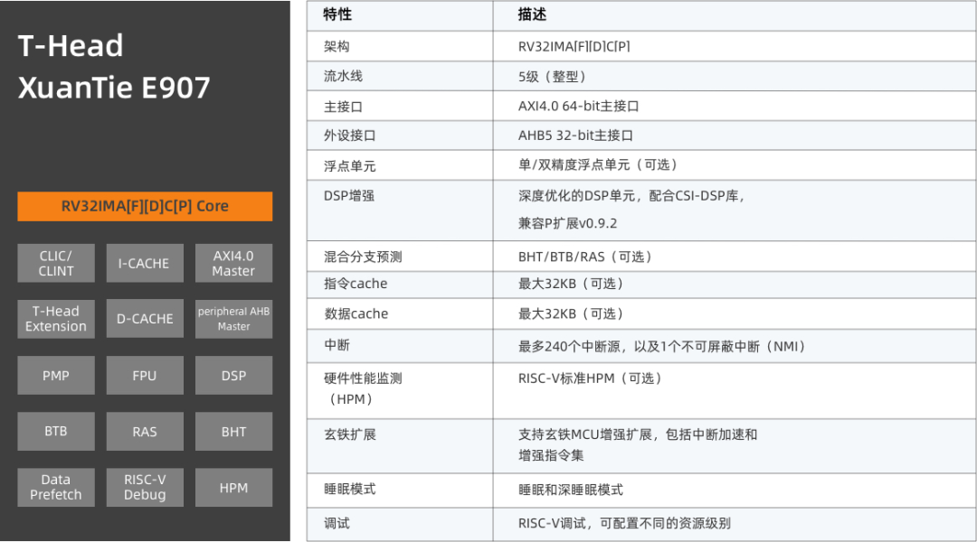
In the V85x platform, the E907 uses RV32IMAC, excluding the P instruction set.
V85x Platform Block Diagram
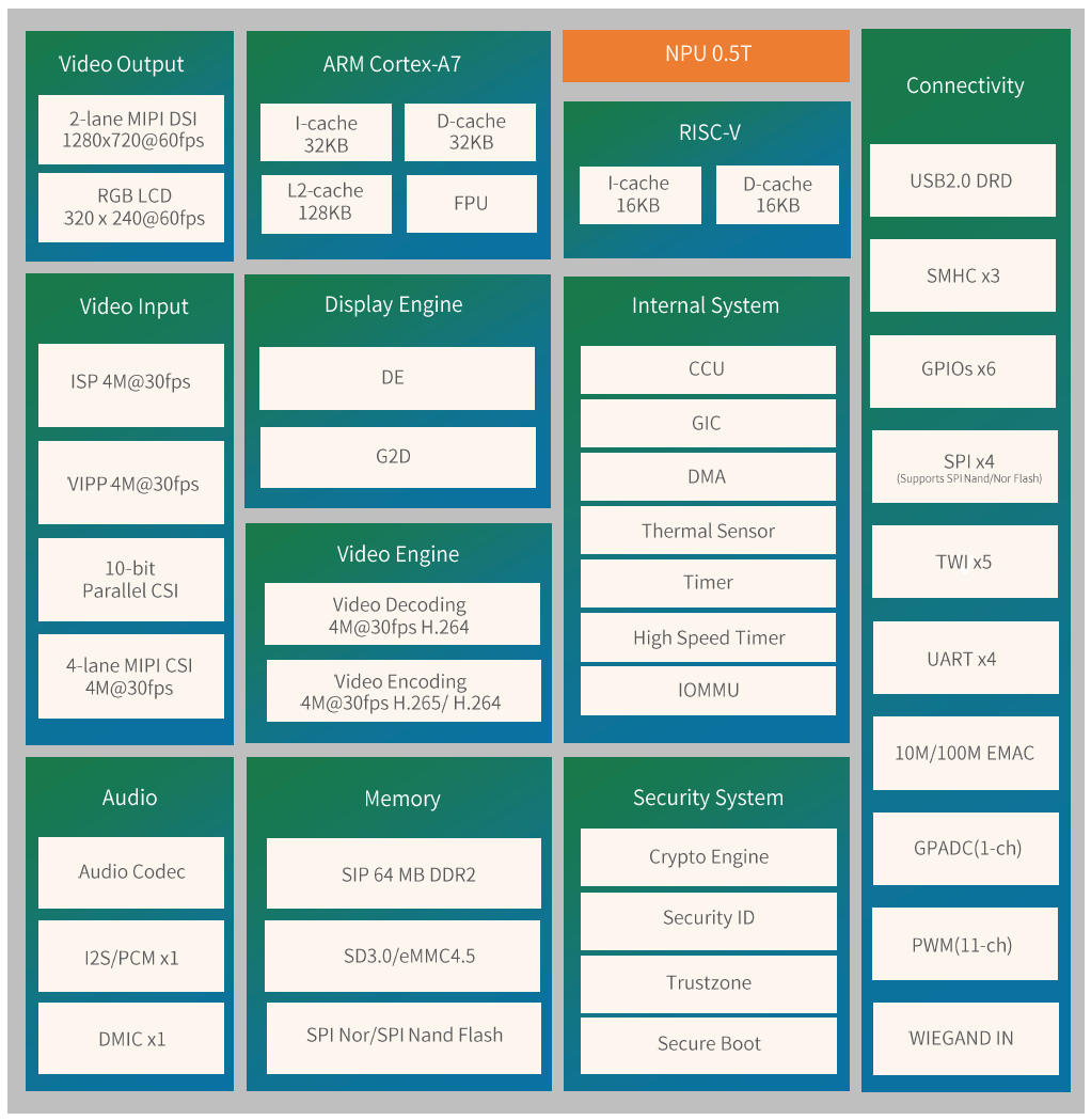
Block diagram of the V851s chip
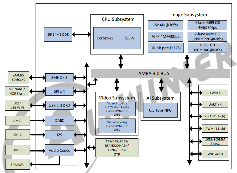
Chip architecture diagram
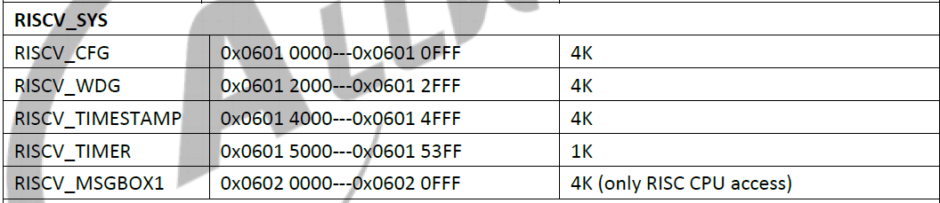
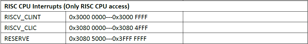
Related memory distribution
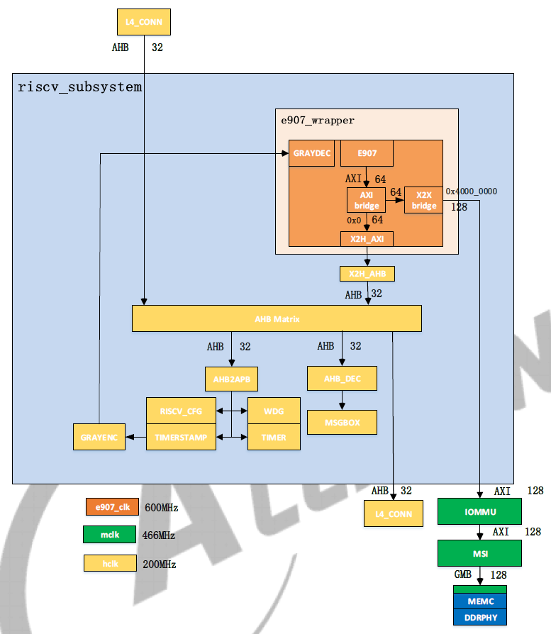
E907 subsystem block diagram
Specific register configuration items will not be elaborated here; please refer to the chip’s datasheet for details.
The heterogeneous system communication in V853 uses MSGBOX at the hardware level and AMP and RPMsg communication protocols at the software level. The A7 core runs a Linux standard RPMsg driver framework, while the E907 is based on the OpenAMP heterogeneous communication framework.
The A7 main core and E907 auxiliary core in the V853 are completely different cores. To maximize their performance and collaboratively complete a task, the systems running on different cores are also different. These different architectures and the software running on them together form an AMP system (Asymmetric Multiprocessing System).
Since the two cores exist to collaborate, a Master – Remote structure often forms in heterogeneous multiprocessing systems. The main core starts the auxiliary core after it is booted. Once both systems on the cores are fully booted, they communicate through IPC (Inter Processor Communication), with RPMsg being one of the IPC methods.
In the AMP system, the two cores communicate through shared memory. They pass messages via AMP interrupts. Memory management is handled by the main core.
Software Adaptation
This part can be developed using the BSP development package, and the device tree configuration is as follows:
reserved-memory { // Configure reserved memory area e907_dram: riscv_memserve { // Memory used by the riscv core reg = <0x0 0x43c00000 0x0 0x00400000>; // Starting address 0x43c00000 length 4MB no-map; }; vdev0buffer: vdev0buffer@0x43000000 { // Reserved memory for vdev device buffer compatible = "shared-dma-pool"; reg = <0x0 0x43000000 0x0 0x40000>; no-map; }; vdev0vring0: vdev0vring0@0x43040000 { // vring device 0 for communication reg = <0x0 0x43040000 0x0 0x20000>; no-map; }; vdev0vring1: vdev0vring1@0x43060000 { // vring device 1 for communication reg = <0x0 0x43060000 0x0 0x20000>; no-map; };}; e907_rproc: e907_rproc@0 { // rproc related configuration compatible = "allwinner,sun8iw21p1-e907-rproc"; clock-frequency = <600000000>; memory-region = <&e907_dram>, <&vdev0buffer>, <&vdev0vring0>, <&vdev0vring1>; mboxes = <&msgbox 0>; mbox-names = "mbox-chan"; iommus = <&mmu_aw 5 1>; memory-mappings = /* DA len PA */ /* DDR for e907 */ < 0x43c00000 0x00400000 0x43c00000 >; core-name = "sun8iw21p1-e907"; firmware-name = "melis-elf"; status = "okay";}; rpbuf_controller0: rpbuf_controller@0 { // rpbuf configuration compatible = "allwinner,rpbuf-controller"; remoteproc = <&e907_rproc>; ctrl_id = <0>; /* index of /dev/rpbuf_ctrl */ iommus = <&mmu_aw 5 1>; status = "okay";}; rpbuf_sample: rpbuf_sample@0 { compatible = "allwinner,rpbuf-sample"; rpbuf = <&rpbuf_controller0>; status = "okay";}; msgbox: msgbox@3003000 { // msgbox configuration compatible = "allwinner,sunxi-msgbox"; #mbox-cells = <1>; reg = <0x0 0x03003000 0x0 0x1000>, <0x0 0x06020000 0x0 0x1000>; interrupts = <GIC_SPI 0 IRQ_TYPE_LEVEL_HIGH>, <GIC_SPI 1 IRQ_TYPE_LEVEL_HIGH>; clocks = <&clk_msgbox0>; clock-names = "msgbox0"; local_id = <0>; status = "okay";}; e907_standby: e907_standby@0 { compatible = "allwinner,sunxi-e907-standby"; firmware = "riscv.fex"; mboxes = <&msgbox 1>; mbox-names = "mbox-chan"; power-domains = <&pd V853_PD_E907>; status = "okay";};
Memory Allocation
In the device tree configuration, the memory used by the small core is included, such as memory for the small core itself, device communication memory, loopback memory, etc. Here, the E907 runs in DRAM. The starting memory address can be found in the datasheet.
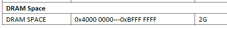
Generally, we set the memory address to the end, for example, the V851s used here has 64MByte memory, so the memory range is 0x40000000 – 0x44000000, and we configure it to 0x43c00000. For V853s with 128M memory, it can be set to 0x47C00000, and so on. The swap memory can be configured nearby.
reserved-memory { // Configure reserved memory area e907_dram: riscv_memserve { // Memory used by the riscv core reg = <0x0 0x43c00000 0x0 0x00400000>; // Starting address 0x43c00000 length 4MB no-map; }; vdev0buffer: vdev0buffer@0x43000000 { // Reserved memory for vdev device buffer compatible = "shared-dma-pool"; reg = <0x0 0x43000000 0x0 0x40000>; no-map; }; vdev0vring0: vdev0vring0@0x43040000 { // vring device 0 for communication reg = <0x0 0x43040000 0x0 0x20000>; no-map; }; vdev0vring1: vdev0vring1@0x43060000 { // vring device 1 for communication reg = <0x0 0x43060000 0x0 0x20000>; no-map; };};Then, the link script for the e907 needs to be configured. Find e907_rtos/rtos/source/projects/v851-e907-lizard/kernel.lds and set the ORIGIN to the reserved memory above.
MEMORY{ /*DRAM_KERNEL: 4M */ DRAM_SEG_KRN (rwx) : ORIGIN = 0x43c00000, LENGTH = 0x00400000}Next, configure the small core’s defconfig located in e907_rtos/rtos/source/projects/v851-e907-lizard/configs/defconfig accordingly.
CONFIG_DRAM_PHYBASE=0x43c00000CONFIG_DRAM_VIRTBASE=0x43c00000CONFIG_DRAM_SIZE=0x0400000
Configuring the Startup of the Small Core
The process for configuring the startup of the small core is as follows; here we only discuss the case of starting the small core using Linux, not the fast boot related aspects.
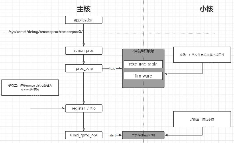
1. Load the firmware
-
Call the firmware interface to obtain the firmware from the filesystem
-
Parse the resource_table segment of the firmware, which contains the following: declaration of required memory (allocated by Linux, configured in the device tree), declaration of the vdev used (fixed to one), declaration of the vring used (fixed to two)
2. Register the rpmsg virtio device
-
Provide vdev->ops (implemented based on the virtio interface)
-
Match with the rpmsg_bus driver to complete rpmsg initialization
3. Start the small core
-
Call rproc->ops->start
Loading Firmware
The driver is located at kernel/linux-4.9/drivers/remoteproc/sunxi_rproc_firmware.c
First, call the sunxi_request_firmware function
int sunxi_request_firmware(const struct firmware **fw, const char *name, struct device *dev){ int ret, index; struct firmware *fw_p = NULL; u32 img_addr, img_len; ret = sunxi_find_firmware_storage(); if (ret < 0) { dev_warn(dev, "Can't find boot_package head\n"); return -ENODEV; } index = ret; ret = sunxi_firmware_get_info(dev, index, name, &img_addr, &img_len); if (ret < 0) { dev_warn(dev, "failed to read boot_package item\n"); ret = -EFAULT; goto out; } ret = sunxi_firmware_get_data(dev, index, img_addr, img_len, &fw_p); if (ret < 0) { dev_err(dev, "failed to read Firmware\n"); ret = -ENOMEM; goto out; } *fw = fw_p;out: return ret;}The driver will read from a specific location in the firmware, using the function sunxi_find_firmware_storage, which will look for the firmware in fixed locations including lib/firmware, /dev/mtd0, /dev/mtd1, /dev/mmcblk0, etc. For Linux startup, we only need to place it in lib/firmware.
static int sunxi_find_firmware_storage(void){ struct firmware_head_info *head; int i, len, ret; loff_t pos; const char *path; u32 flag; len = sizeof(*head); head = kmalloc(len, GFP_KERNEL); if (!head) return -ENOMEM; ret = sunxi_get_storage_type(); for (i = 0; i < ARRAY_SIZE(firmware_storages); i++) { path = firmware_storages[i].path; pos = firmware_storages[i].head_off; flag = firmware_storages[i].flag; if (flag != ret) continue; pr_debug("try to open %s\n", path); ret = sunxi_firmware_read(path, head, len, &pos, flag); if (ret < 0) pr_err("open %s failed, ret=%d\n", path, ret); if (ret != len) continue; if (head->magic == FIRMWARE_MAGIC) { kfree(head); return i; } } kfree(head); return -ENODEV;}Configuring the Clock
Configure the clk and boot options for the small core. The driver is located at kernel/linux-4.9/drivers/remoteproc/sunxi_rproc_boot.c for reference.
struct sunxi_core *sunxi_remote_core_find(const char *name); int sunxi_core_init(struct sunxi_core *core); void sunxi_core_deinit(struct sunxi_core *core); int sunxi_core_start(struct sunxi_core *core); int sunxi_core_is_start(struct sunxi_core *core); int sunxi_core_stop(struct sunxi_core *core); void sunxi_core_set_start_addr(struct sunxi_core *core, u32 addr); void sunxi_core_set_freq(struct sunxi_core *core, u32 freq);Using DEBUGFS to Load Firmware
Since the interface has already been registered externally, you only need to use commands to start the small core. Assuming the small core’s ELF name is e907.elf and it has been placed in the lib/firmware folder.
echo e907.elf > /sys/kernel/debug/remoteproc/remoteproc0/firmware echo start > /sys/kernel/debug/remoteproc/remoteproc0/state
Development of the E907 Core
A real-time operating system (RTOS) is provided for development, based on the RTT kernel.
Original link:https://github.com/YuzukiHD/Yuzukilizard/tree/master/S2oftware/BSP/e907_rtos
Additionally, the Docker image already contains this development package for direct use.
Using Docker
Simply pull the image gloomyghost/yuzukilizard.
docker pull gloomyghost/yuzukilizard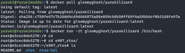
Setting Up a Development Environment Independently
Use the git command to download (do not download the zip directly from Github, as it will break hyperlinks and file attributes).
git clone --depth=1 https://github.com/YuzukiHD/Yuzukilizard.git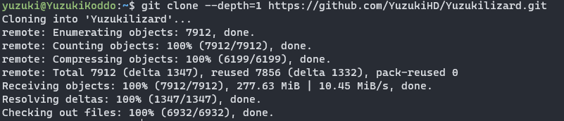
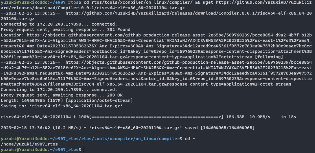
Then copy it to the current directory.
cp -rf Yuzukilizard/Software/BSP/e907_rtos/ . && cd e907_rtosDownload the compilation toolchain to the specified directory.
Compiling the First ELF System
Enter the rtos/source folder.
cd rtos/source/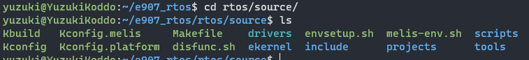
Apply environment variables and load the scheme.
source melis-env.sh; lunch
Then compile directly; it will automatically unpack the configuration toolchain. After compilation, the firmware can be found in ekernel/melis30.elf.
make -j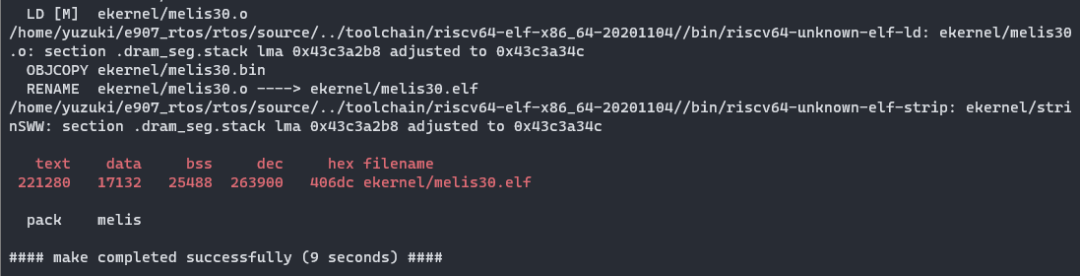
The compilation framework for the small core is similar to that of the kernel, using kconfig as the configuration item. Use make menuconfig to enter the configuration page.
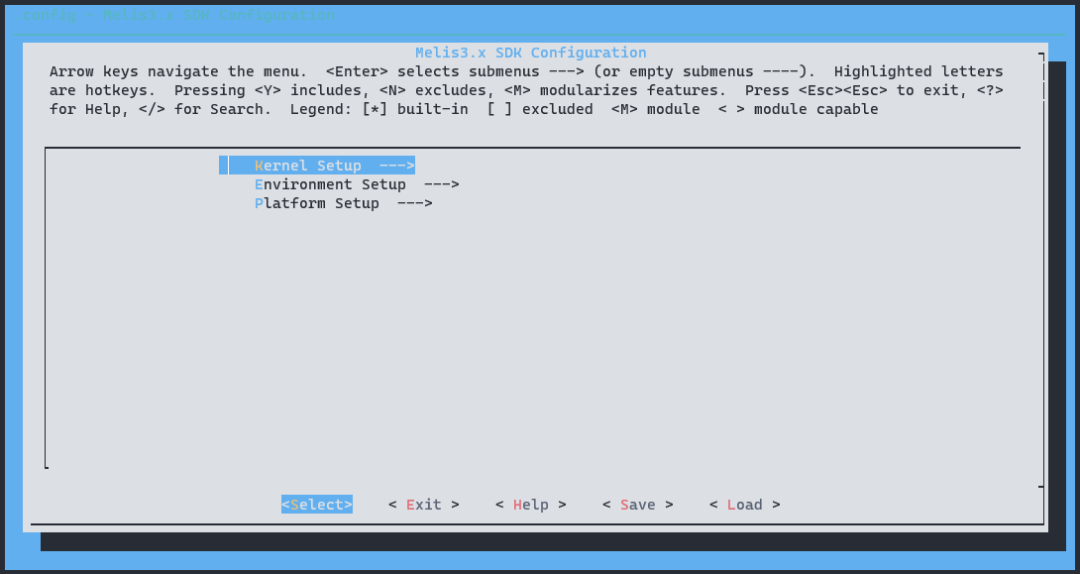
The rest of the usage is the same as the standard menuconfig, which will not be elaborated here.
Using UART for Console Output on the Small Core
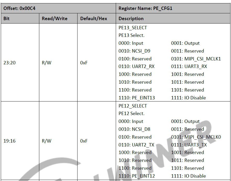
First, configure the PINMUX editing file for the small core at e907_rtos/rtos/source/projects/v851-e907-lizard/configs/sys_config.fex. Here, UART3 is used, with pins PE12, PE13, and mux set to 7.
[uart3] uart_tx = port:PE12<7><1><default><default> uart_rx = port:PE13<7><1><default><default>Then configure to use uart3 as output, run make menuconfig to enter the configuration.
Kernel Setup ---> Drivers Setup ---> Melis Source Support ---> [*] Support Serial Driver SoC HAL Drivers ---> Common Option ---> [*] enable sysconfig // Enable reading and parsing sys_config.fex functionality UART Devices ---> [*] enable uart driver // Enable driver [*] support uart3 device // Use uart3 (3) cli uart port number // cli configured to uart3 Subsystem support ---> devicetree support ---> [*] support traditional fex configuration method parser. // Enable sys_config.fex parserIn Linux, configure the device tree to match the corresponding pins and mux.
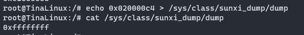
If the device tree does not configure the pins and mux, the kernel will kindly set unused pins to io_disable. Since the UART device is operated using iommu, this will cause io to be unusable. As shown below.
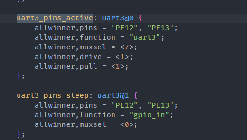
Additionally, the uart3 node needs to be configured as disabled; otherwise, the kernel will prioritize this device.
&uart3 { pinctrl-names = "default", "sleep"; pinctrl-0 = <&uart3_pins_active>; pinctrl-1 = <&uart3_pins_sleep>; status = "disabled";};If configured to okay, the following prompt will appear.
uart: create mailbox fail uart: irq for uart3 already enabled uart: create mailbox failAfter starting the small core firmware, you can see the output.
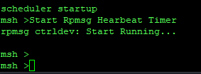
Core Communication
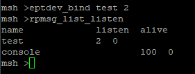
After starting the small core, use eptdev_bind test 2 to establish two communication nodes for listening. You can use the rpmsg_list_listen command to view the listening nodes.
Then create communication nodes on the Linux side. Since we enabled two listeners above, we will also open two nodes here.
echo test > /sys/class/rpmsg/rpmsg_ctrl0/open echo test > /sys/class/rpmsg/rpmsg_ctrl0/open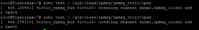
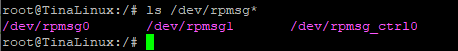
You can then see the communication nodes /dev/rpmsg0 and /dev/rpmsg1 under /dev/.
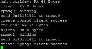
You can also see the establishment of nodes on the small core console.
Linux -> e907
You can directly operate the nodes on the Linux side, using echo to write data.
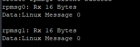
echo "Linux Message 0" > /dev/rpmsg0 echo "Linux Message 0" > /dev/rpmsg1
The small core will receive the data.
e907 -> Linux
Use the command eptdev_send to send data.
eptdev_send 0 "E907 Message" eptdev_send 1 "E907 Message"
On the Linux side, you can read it out directly.
cat /dev/rpmsg0 cat /dev/rpmsg1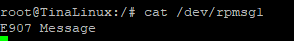
You can keep listening, for example, sending data multiple times.
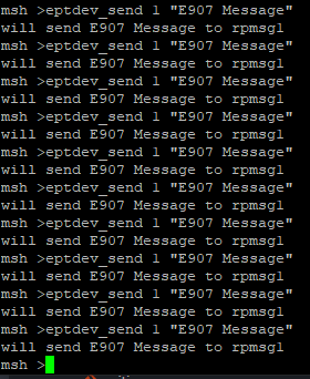
The data obtained on the Linux side will also increase.

Closing Communication
On the Linux side, close the control node by echoing to the node.
echo 0 > /sys/class/rpmsg/rpmsg_ctrl0/close echo 1 > /sys/class/rpmsg/rpmsg_ctrl0/close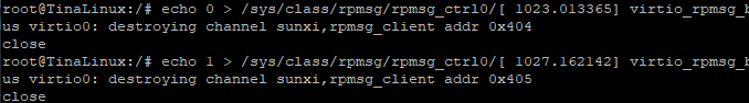
At the same time, E907 will also print the link closure.

RPMsg Notes
-
Endpoints are the basis of rpmsg communication; each endpoint has its own src and dst addresses, with a range of (1 – 1023, except 0x35).
-
The maximum data sent by rpmsg each time is 512 – 16 bytes; (the data block size is 512, with the header occupying 16 bytes).
-
rpmsg uses a name server mechanism; when the endpoint name created by E907 is the same as the rpmsg driver name registered in Linux, the rpmsg bus will call its probe interface. Therefore, if you need the Linux side to actively initiate the creation of an endpoint and notify e907, you need to use the aforementioned rpmsg_ctrl driver.
-
rpmsg calls back serially, so it is recommended not to call long-running functions in the rpmsg_driver callback to avoid affecting the operation of other rpmsg drivers.
Custom Small Core APP
The entry point for the small core program is located at e907_rtos/rtos/source/projects/v851-e907-lizard/src/main.c
#include <stdio.h> #include <openamp/sunxi_helper/openamp.h> int app_entry(void *param){ return 0;}You can customize the program that runs on the small core.
Custom Small Core Commands
The SDK provides the FINSH_FUNCTION_EXPORT_ALIAS binding method, specifically:
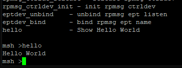
FINSH_FUNCTION_EXPORT_ALIAS(<function_name>, <command>, <command_description>)For example, to write a hello command that outputs “Hello World” with the description “Show Hello World”:
int hello_cmd(int argc, const char **argv){ printf("Hello World\n");} FINSH_FUNCTION_EXPORT_ALIAS(hello_cmd, hello, Show Hello World)This command can then be found and executed on the small core.
-End-