ver0.2
Introduction
Happy holidays, everyone! I hope you all stay happy forever, as we are all still kids at heart.
In the previous article, we introduced the PCSA system architecture based on SCP as the core, with PCF as the hardware framework and OPSM as the upper management strategy. After gaining a basic understanding of hardware-related power management in the ARM architecture, this article will delve deeper into how the power management mechanism built around SCP operates. We will discuss how ARM abstracts the power manager and the managed objects into a model, and how to maximize the utilization of power resources on the SoC platform through software and hardware means. Before reading this article, I hope everyone will read our previous articles to grasp some basics and get a feel for the topic:
(1) [V-02] Basics of Virtualization – CPU Architecture (Based on AArch64)
(2) [A-03] ARMv8/ARMv9 – Multi-level Cache Architecture
(3) [A-21] ARMv8/v9 – Overview of SMMU System Architecture and Functions
(4) [A-25] ARMv8/v9 – System Architecture of GIC (Hardware Foundation of Interrupts)
(5) [A-38] ARMv8/v9 – Generic Timer System Architecture
(6) [A-41] ARMv9/v8 – Power Management System Architecture
Main Content
1.1 Power Management Model
Before introducing ARM’s power management model, we need to understand the ARM-based SoC model, as shown in Figure 1-1.

Figure 1-1 ARM SoC System Architecture
ARM connects various IP subsystems into a SoC through a bus and bus-compatible interfaces, and these IPs require power supply from the SoC to operate. Unlike our home electrical network, the power supply system of an SoC is more complex. Home electrical systems generally just need to be ON/OFF, while the power supply on an SoC must also consider efficiency. To put it bluntly, it must maintain the normal operation of the entire SoC while minimizing energy consumption and heat generation. This “both-and” requirement seems unreasonable, but chip manufacturers have silently accepted it and are continuously competing in the power management arena. Poor power management in a product can significantly reduce its market competitiveness. Therefore, modern SoC systems generally delegate power management tasks to a dedicated power management chip (PMIC), which in the ARM ecosystem is the SCP, creating an Always-on subsystem around this chip to manage the power needs of the SoC. (Consider why it needs to be Always-on.)
With the SoC model established, ARM further abstracts the power management architecture around SCP into the following power management model, as shown in Figure 1-2.
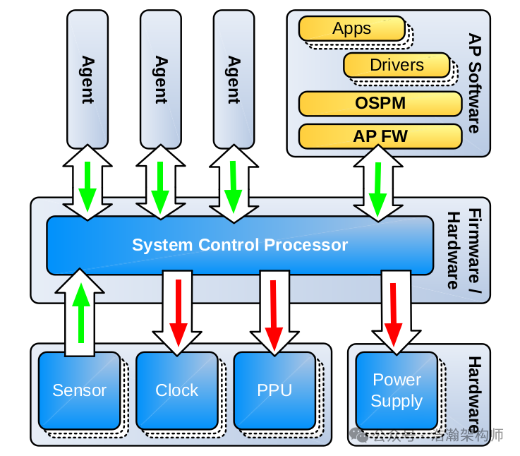
Figure 1-2 System Control Processor Concept
Let’s first look at the description of this power management model in the manual:
The application processor (AP) software stack is shown as a requestor of SCP services. Other agents in the system might also have the capability to directly generate requests for resources that the SCP controls. Examples of such agents might be a modem subsystem in a mobile SoC or a management function in a server SoC. The SCP reconciles requests from all agents, managing the availability of shared resources and power-performance limits according to all constraints.
Combining Figures 1-1 and 1-2, along with the manual’s description, we can summarize the ARM SoC power management model as follows:
(1) First, the power management work of ARM logically adheres to a central point, which is the SCP. On different chip platforms, the SCP is the specific PMIC chip. From the perspective of the SoC system architecture, the SCP is a power management chip integrated into the Always-ON subsystem.
(2) Each IP on the SoC is abstracted into agents connected to the SCP. An agent can be a dedicated IP, such as a CPU (Application Processor), or a subsystem composed of a group of IPs, such as the multimedia subsystem (GPU/VPU/DPU) of the SoC, or another relatively independent subsystem controlled by SCP. These agents must accept management from SCP during operation while also being able to request SCP to meet their current operational needs (increase frequency when busy, decrease frequency to improve battery efficiency when idle).
(3) In addition to aggregating the demands of various agents, the SCP must also consider the state of the SoC, such as the current temperature of the SoC. The SCP must keep track of this information and feedback it to each agent, allowing them to adjust their workload according to established strategies and make decisions to protect the SoC hardware. For example, if the SoC temperature exceeds the upper limit of the operating temperature, it must proactively shut down some IPs or even the entire SoC to ensure the safety of the current SoC.
(4) After the SCP aggregates the system information and agent requests (the green arrows in Figure 1-2), how does it perform power control? The red arrows in Figure 1-2 indicate the direction of control commands flow, primarily controlling clocks, PPU (Power State Management), and the power supply system.
(5) To perform these complex tasks, the SCP requires independent programming, and these program codes are permanently fixed in the SCP’s internal storage system in the form of firmware, which cannot be easily changed or customized. In fact, the firmware running on the SCP is the core implementation of ARM’s power management system mechanism.
1.2 SCP Services
As the core node of power management, the services provided by SCP are also detailed in the manual:
The SCP provides the following primary services:
• OSPM directed operation: The SCP performs voltage supply changes, power control actions, and clock source management under the direction of the OSPM. These services might also be used by other requesting agents.
• Response to system events: The SCP responds to system events with appropriate power, clock, reset, and system control actions. These actions include:
– Timer events: The SCP has local timer resources that can be used for the triggering of system wakes and any periodic actions such as monitoring.
– Wake events: Responding to wake requests including GIC wake requests, caused by interrupts routed to powered-off cores, and system access requests from other agents.
– Debug access power control: Responding to requests from the debug access port and related controls, including power management of the debug infrastructure.
– Watchdog events and system recovery actions: On a local watchdog timeout, the SCP can execute a reset and re-initialization sequence.
• System aware functions: The SCP can act autonomously and can perform functions such as the following:
– The SCP can reconcile requests from OSPM and other agents for shared resources. For example, it can control the path to main memory or entry to, and exit from, SoC sleep modes without requiring AP core activity.
– The SCP can take responsibility for monitoring sensors and measurement functions. Monitoring tasks might include process and temperature sensor data harvesting and associated actions such as operating point optimization and alarm conditions.
– The role of the SCP in operating point selection can extend to overriding the OSPM direction, as necessary, to ensure the electrical and thermal protection of the system.
• System initialization: The SCP takes responsibility for power-on reset system initialization tasks, from power-on sequencing of the primary system and AP core power domains through to AP boot.
The SCP abstracts both tasks and details away from the OSPM, enabling increased use of AP core low-power states
and a simplified board support package (BSP) implementation. At the same time, platform specific differentiation, fixes, and improvements can be implemented at firmware level by the silicon provider or OEM.
1.2.1 OSPM Directed Operation
OSPM can be understood as the strategy provider for interactions between various agents and the SCP, as shown in Figure 1-3:
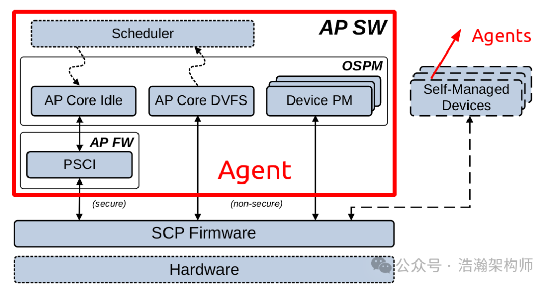
Figure 1-3 Simplified Power Management Software Stack
Within an SoC system, there will be multiple agents, and each agent can have its own OSPM module to interact with the SCP. However, considering coordination in time and space, typically, there will not be so many agents running full-stack OSPM modules within an SoC system. In most cases, various cooperating IPs delegate their power control strategies to the OSPM running on the CPU for unified scheduling. This part will also be a focus of our later research.
1.2.2 Response to System Events
As we mentioned earlier when introducing the SCP, ARM positions the SCP subsystem as a complete small SoC system embedded within the SoC, equipped with the basic components necessary for the SoC to function (UFS, Memory, Peripherals…). When the entire SoC system enters a low-power state, the SCP operates in the Always-On hardware block, meaning everyone else can rest while it must always keep an eye on the operational state of the entire SoC system, such as responding to events sent by timers, as shown in Figure 1-4:
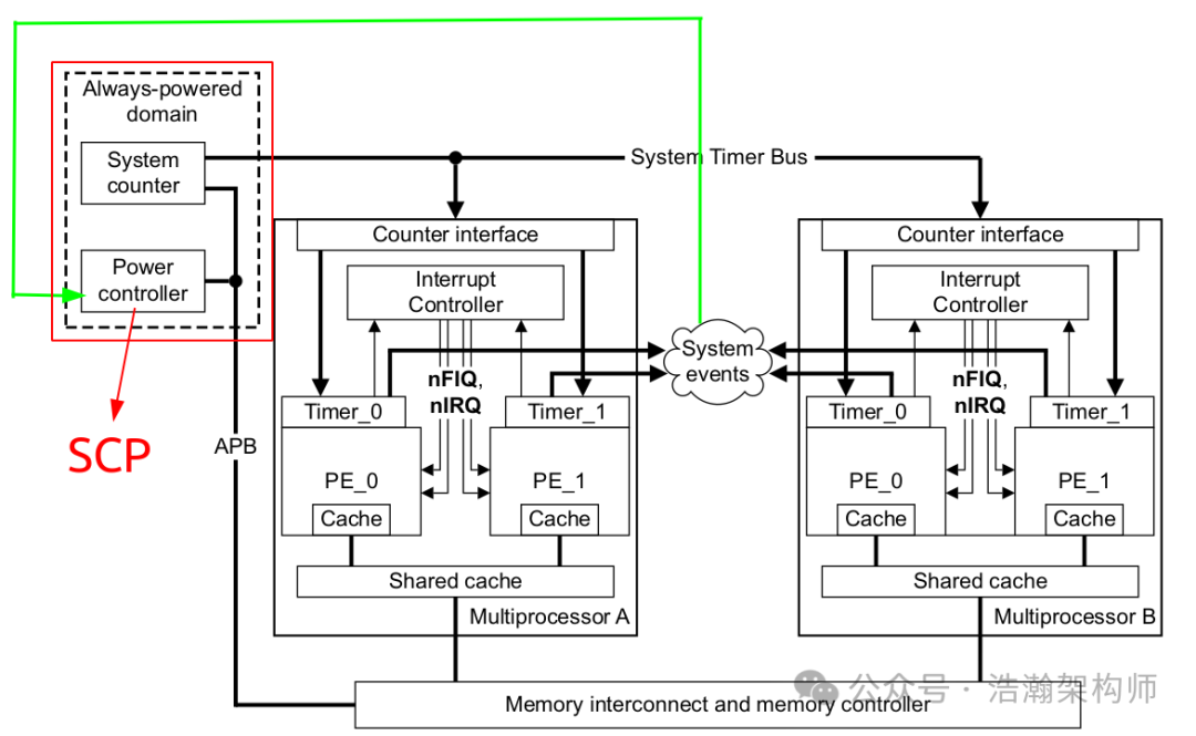
Figure 1-4 Generic Timer Example
Let’s refer to the description in the Generic Timer manual:
The Generic Timer can also be used to generate an event stream as part of the Wait for Event mechanism. The WFE instruction puts the core into a low power state, with the core woken by an event.
There are several ways to generate an event, including:
• Executing the SEV (Send Event) instruction on a different core
• Clearing the Global Exclusive Monitor of the core
• Using the Event stream from the core’s Generic Timer
The Generic Timer can be configured to generate a stream of events at a regular interval. One use for this configuration is to generate a timeout. WFE is typically used when waiting for a resource to become available, when the wait is not expected to be long. The event stream from the timers means that the maximum time that the core will stay in the low power state is bounded.
The system counters provide a common time reference for the SoC. Generic timers use the counter values to produce interrupts and wake-up events. The primary system counter value is distributed to other system elements, including application processors and debug infrastructure, to provide a consistent view of time.
The primary system counter resolution requires a clock source that, due to power consumption reasons, might be turned off in SoC SLEEP states. The provision of a secondary constantly running low-speed counter, typically using a real-time clock source as its input, enables the required view of time to be preserved through SoC SLEEP states. Generic timers using this counter are used to generate wake-up events in these states.
The SCP is responsible for managing the transfer of time between these system counters at entry to and exit from SLEEP states to ensure a consistent view of time is presented to the system. This can be achieved with a combination of hardware and firmware capability in the SCP.
For the SCP microcontroller, the system events generated by the timer are interrupts that require a response from the SCP. The SCP must quickly decide based on the strategies configured in the firmware whether to wake the entire system or maintain the low-power state.
1.2.3 System Aware Functions
The SCP needs to have the ability to operate independently of CPU management, with the most typical example being the decision-making capability under the feedback system of sensors, as shown in Figure 1-5:
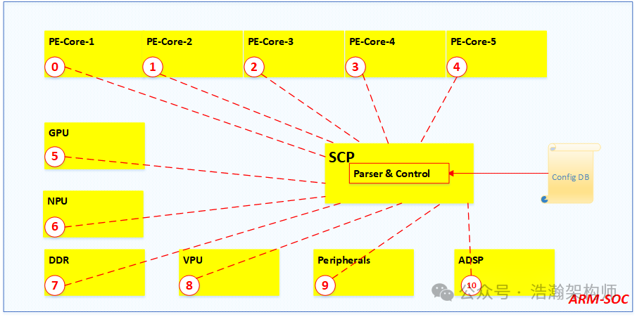
Figure 1-5 SOC Temperature Sensors Layout Example
Chip manufacturers on the SoC platform will place temperature sensors at various points to monitor the temperature information of the system in real-time. After the SCP aggregates this temperature information, it can make real-time decisions based on the configuration, as shown in Figure 1-6:
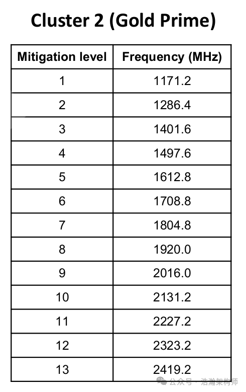
Figure 1-6 Frequency and Mitigation Levels Mapping
The above figure shows a configuration from a certain vendor regarding the big core, clearly dividing the execution state of the PE-Core into 13 levels. Based on temperature changes, the SCP can directly adjust the execution frequency of the PE-Core to the corresponding level, and this adjustment process does not require CPU involvement.
Power state management of the SoC also does not require PEs to participate, as shown in Figure 1-7:
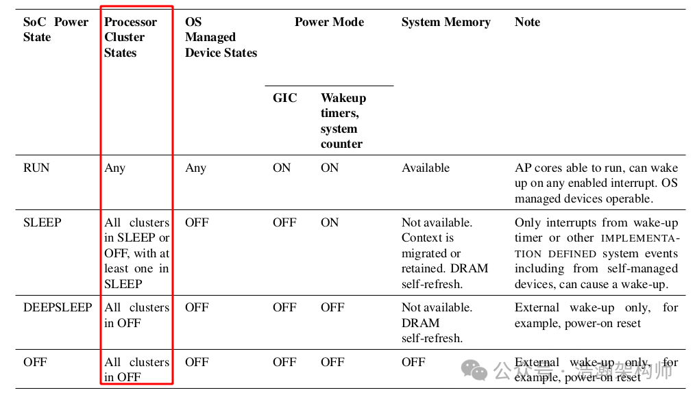
Figure 1-7 SoC Power States
Regarding the topic of ARM’s power management states, we will plan a dedicated article to discuss it later. Here, we first look at the power states of the SoC divided into RUN, SLEEP, DEEPSLEEP, and OFF. In these power states, except for RUN, all other states have the PEs in sleep or off states, and the management of the entire SoC’s power state also needs to be completed by the SCP without PE participation.
1.2.4 System Initialization
Let’s switch to a more macro perspective to examine the relationship between the SCP and the SoC system startup, as shown in Figure 1-8:
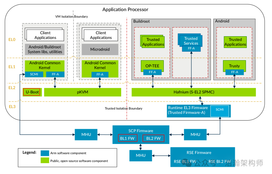
Figure 1-8 Runtime View of Total Compute 2023 Software Stack
Let’s look at the description in the manual:
The SCP is a Trusted CPU and will always run Trusted code. Therefore, all the regions of the SCP memory map that are not mapped to the Application Processor (AP) Memory Map are Secure by default.
A boot ROM and an on-chip SRAM are mapped in the bottom 512MB of the address space. The first 1MB of the top 512MB of address space is reserved for the Private Peripheral Bus (PPB).
This region is further divided into the following spaces:
Internal PPB
The Internal PPB space is the bottom 256KB of the PPB space and is accessed through an Advanced High-performance Bus Lite (AHB-Lite) bus with the SCP subsystem. The following Cortex-M85 system components are in this space:
• System Control Space (SCS)
• Flash Patch and Breakpoint (FPB)
• Data Warehouse Trace (DWT)
• Instrumentation Trace Macrocell (ITM)
The processor (SCP) has ROM for boot and RAM for storing firmware instructions and data. The ROM and RAM are private to the SCP.
A possible implementation is that the ROM is used at boot to bring the system to a state where a host processor can access the memory system and load, either directly or indirectly, the SCP firmware.
The SCP firmware code and data spaces are entirely within its private RAM. The SCP can then operate while the
remainder of the SoC is off and system memory is unavailable. However, when available, the SCP can access system memory and other parts of the system as required.
Let’s also look at the U-Boot startup process as shown in Figure 1-9:
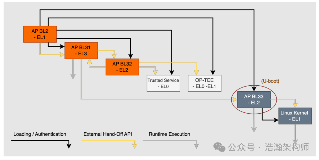
Figure 1-9 U-Boot Flow
From Figures 1-8 and 1-9, combined with the manual’s description, we can see that the system initialization is primarily completed during the system startup phase. As the power manager of the entire system, the SCP controls the power sequencing of the entire SoC system and the clock frequencies of various IPs, and is also the secure node in the SoC by default. Therefore, one of the core services of the SCP is to control the initialization tasks of the SOC system during the startup phase, such as accepting requests from the AP and activating the GIC controller at the appropriate time, allowing other IPs and PE-Cores in the system to start communicating through interrupt signals. The topic of system startup is temporarily beyond the scope of our research on power, and we will plan a dedicated article to study it later. Here, it is sufficient for everyone to understand the basic knowledge related to the SCP and ARM system startup. Additionally, the introduction to security has only scratched the surface, and we have not systematically organized it yet, so it is not appropriate to elaborate on it here.
Although this part may not be accessible to ordinary programmers, it still has research value. Here’s a requirement to consider: In a virtualized architecture on an SoC system, three systems are running, and these three systems use IPA and PA to map physical memory. The system’s DDR has 24GB of physical space, and one VM (Android) is allocated the address space from 16GB to 24GB. At this time, an IP (e.g., WiFi/BT) on the SoC system can only access a 32-bit address space (4GB), and this IP needs to be passed through to the VM (Android). How should the startup process be configured to complete the system initialization? As a qualified system architect and virtualization engineer, this topic requires a deep understanding of the startup process to solve. This is also a typical use case for system initialization.
1.2.5 Other Services
We have introduced the basic services of the core node of power management, the SCP, on the ARM platform. These services are actually carried out by the firmware running in the SCP chip. Here, we have only provided some extended descriptions based on the manual, but in reality, the services of the SCP are quite complex, as shown in Figure 1-10:
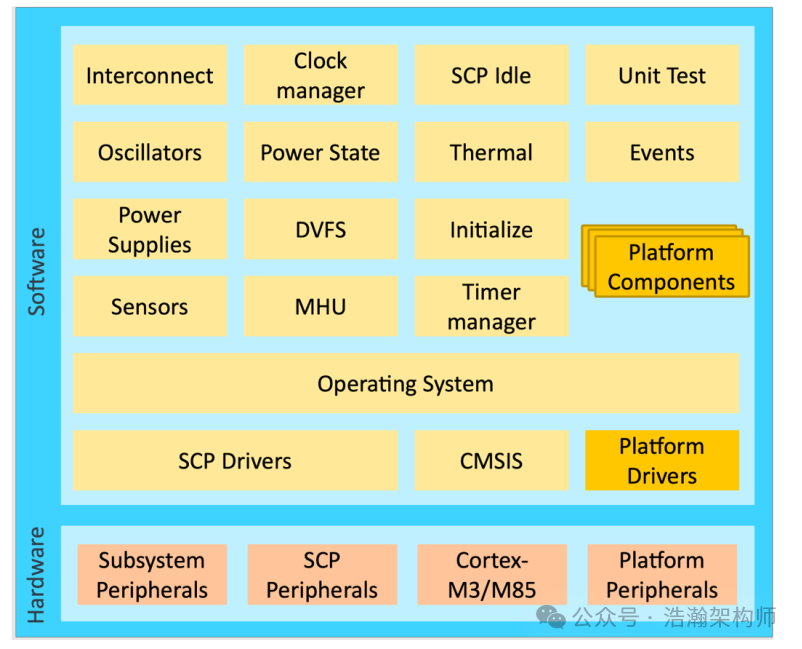
Figure 1-10 SCP Hardware and Software Stack Architecture Overview
It can be seen that in addition to the basic services within the SCP (Drivers & OS), the upper-level services are quite rich. All these services are designed to support power management work on the ARM platform. Some of these services are transparent to other agents, while others require requests from other agents (OSPM). Our focus of research will be on these modules that accept OSPM requests, such as DVFS, Thermal, etc. Due to space limitations, we will not elaborate on them here.
Conclusion
In this article, we started the discussion from the Always-on system architecture, leading to the ARM platform’s power management model. ARM introduces a core service node to aggregate requests from various agents, and after summarizing, it feeds back the decision signals to the various agent components on the SoC system to achieve management objectives. Due to space limitations, we have only introduced some basic services within the SCP. In future articles, we will also discuss the granularity of SCP management work and power modes (which have already been written but are too lengthy, so they will be published in several articles). That’s all for today. Please follow, comment, and share. Thank you all. Finally, I hope that no matter how many years you travel, you will always return to that happy and carefree childhood.