
Share interest, spread happiness,
increase knowledge, and leave beautiful.
Dear, this is the LearingYard Academy!
Today, I will bring you “51 microcontroller basics”
Welcome to visit!
Mind mapping
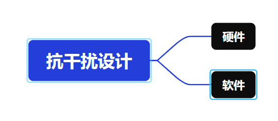
In the hardware anti-interference design of 51 microcontroller systems, power supply purification is the primary task. The AC input requires varistors and common-mode inductors to suppress surges and common-mode interference, while the DC side employs multi-stage filtering networks (such as electrolytic capacitors, ceramic capacitors, and TVS diodes) to ensure stable power supply. PCB layout must strictly adhere to high-frequency circuit standards, including shortening crystal oscillator traces, separating digital/analog grounds, widening power trace widths, and prioritizing a four-layer board structure to optimize electromagnetic compatibility. The signal processing stage requires optocoupler isolation or Schmitt trigger shaping for input signals, while output drive circuits should incorporate buffer resistors and freewheeling diodes. All external interfaces (e.g., RS485) need TVS diodes and termination resistors to establish comprehensive hardware-level protection.
Software anti-interference design focuses on enhancing system fault tolerance. The hardware watchdog timer serves as the last line of defense and must be regularly reset within program loops and critical tasks. Important data storage employs redundancy strategies such as XOR checks or complementary backups to ensure data reliability. Input signals undergo median or mean filtering through multiple samplings to eliminate jitter interference. During system operation, periodic RAM self-tests and code CRC verification help promptly detect hardware failures or program tampering. For timing-sensitive operations (e.g., EEPROM writes), interrupts should be temporarily disabled to avoid interference, while communication protocols incorporate error detection mechanisms like CRC checks, forming a multi-layered software protection system.
Customized solutions are required for different interference sources. In motor control applications, RC snubber circuits should be connected in parallel across motor terminals for hardware protection, while software implementations insert critical code protection segments during PWM output. In high-interference industrial environments, fiber optic isolation or wireless communication can replace wired transmission. Precision measurement systems require special attention to analog circuit shielding and differential signal transmission to suppress common-mode interference. For high-frequency noise-sensitive scenarios, metal shielding enclosures and optimized grounding designs can be added to ensure system stability in complex electromagnetic environments.
Effective anti-interference design requires coordinated optimization of hardware and software. During the design phase, test cases should be developed based on application-specific EMC standards (e.g., IEC 61000), with interference suppression effects quantified using tools such as oscilloscopes and spectrum analyzers. Pre-production compliance testing, including burst pulses and electrostatic discharge tests, should be conducted, with adjustments made to PCB layouts or software algorithms based on the results. For example, an industrial controller’s electrostatic immunity improved from 2kV to 8kV after adding TVS diodes and a software watchdog. This system-level design approach significantly enhances the reliability of 51 microcontrollers in harsh environments, meeting stringent requirements in automotive electronics, industrial control, and other demanding fields.
That’s all for today’s sharing.
If you have a unique idea about the article,
please leave us a message,
and let us meet tomorrow.
I wish you a nice day!
References: Google Translate, Baidu, Bilibili
This article is organized and published by LearningYard Academy. If there is any infringement, please leave a message for communication.

Copywriting & Layout: Twenty-Seven
Reviewed by: Mu Yu