74HC138 is a CMOS 3-to-8 line decoder integrated circuit, featuring 3 input pins and 8 output pins, capable of converting 3 bits of binary data into 8 corresponding output signals. The 74HC138 chip operates within a supply voltage range of 2V to 6V, while the 74LS138 chip operates within a supply voltage range of 4.75V to 5.25V, making it suitable for driving 8 digit integrated 7-segment displays. The former is more suitable for 3.3V microcontroller systems. The 74HC138 chip features fast switching speeds, short response times; due to its use of CMOS technology, it has good noise immunity and anti-interference capabilities; and it possesses strong load driving capabilities, among other advantages.
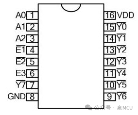
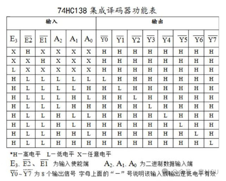
When enabled (E3 is high, /E1 and /E2 are low), input a 3-bit binary number A2A1A0, with values ranging from 000 to 111, corresponding to decimal values 0 to 7. The output provides 8 mutually exclusive low-active outputs (Y0 to Y7), as shown in the truth table below.
74HC164 and 74HC138 are used together to drive an 8-digit common cathode 7-segment display, which is adopted in many circuits due to its strong driving capability and ability to reduce the number of microcontroller ports used.
To minimize hardware resources, the program only occupies one P port of the microcontroller.
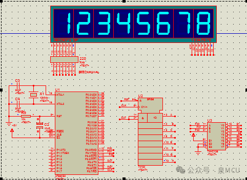
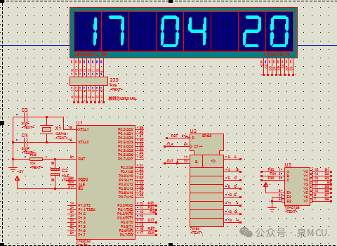
//ch164_138.c // Download successful. The segment that should not be lit is faintly visible when the light is dim. The effect is worse at night. The segment that does not light does not have this phenomenon. Proteus simulation does not show this phenomenon. //-----------------------------------------------------------------// Name: Simulate timing control serial-parallel converter 74HC164 driving one 8-digit integrated 7-segment display //-----------------------------------------------------------------// Description: In this example, two 4-digit integrated displays are driven by one serial-in parallel-out converter 74HC164 + 74HC138 // to display two groups of 8-digit numbers. The segment code driving the 7-segment display only occupies 3 pins of the microcontroller. //-----------------------------------------------------------------#include <reg51.h> // Include 51 microcontroller header file #include <intrins.h> #define INT8U unsigned char // Macro definition, declare variable #define INT16U unsigned int // Macro definition, declare variable #define SCAN P3 // 74HC138 input pins P32-C, P31-B, P30-A // Common anode 7-segment display 0~9, off digit segment code table code INT8U SEG_CODE[] = { 0xC0,0xF9,0xA4,0xB0,0x99,0x92, 0x82,0xF8,0x80,0x90,0xFF }; // Define the two groups of data to be displayed code INT8U tab[2][8]={{1,2,3,4,5,6,7,8}, // First screen display content {1,7,10,0,4,10,2,0}}; // Second screen display content code INT8U scan[]={0x01,0x02,0x04,0x08,0x10,0x20,0x40,0x80}; // 74HC164 pin definitions sbit DAT = P3^4; // Serial data line 164_Pin1_2 sbit CLK = P3^7; // Serial clock line 164_Pin_8 sbit RST = P3^6; // Reset pin 164_Pin_9 // Function declarations void delay_ms(INT16U x); // Declare delay 1ms function void Serial_Output(INT8U d); // Declare serial-in parallel-out function //-----------------------------------------------------------------// Main program //-----------------------------------------------------------------void main(void){ INT8U i,j,k; while(1) // Infinite loop { for(i=0;i<2;i++) // 2 groups of data for(j=0;j<200;j++) // Repeat 200 times for one screen for(k=0;k<8;k++) // One screen needs to send 8 segment codes and 8 scan codes { // No clear screen statement is also acceptable RST = 0; // Reset 74HC164, output is 0 RST = 1; // Pull up reset pin, allow 74HC164 to output Serial_Output(0x00); // Send clear screen segment code RST = 0; // Reset 74HC164, output is 0 RST = 1; // Pull up reset pin, allow 74HC164 to output SCAN = (SCAN & 0xf0) | k; // Send scan code first for better display Serial_Output(~SEG_CODE[tab[i][k]]); // Send segment code last delay_ms(2); } } } //===================== Subfunction Area ==================================== //-----------------------------------------------------------------// Delay 1ms function //-----------------------------------------------------------------void delay_ms(INT16U x){ INT8U i; while(--x) for(i = 0; i < 120; i++) ; } //-----------------------------------------------------------------// Simulate timing to output 1 byte of data serially to 74HC164 //-----------------------------------------------------------------void Serial_Output(INT8U d){ INT8U i; for(i = 0; i < 8; i++) // 1 byte 8 bits { CLK = 0; // Set clock to 0 d <<= 1; DAT = CY; // Shift out one bit (most significant bit first) CLK = 1; // Set clock to 1, rising edge data shifts into 74HC164 } }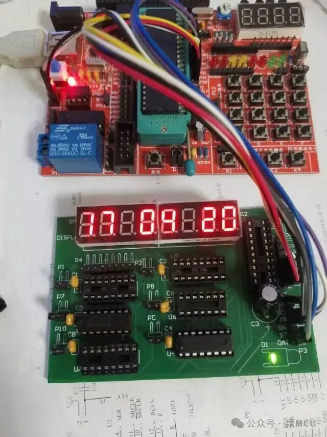
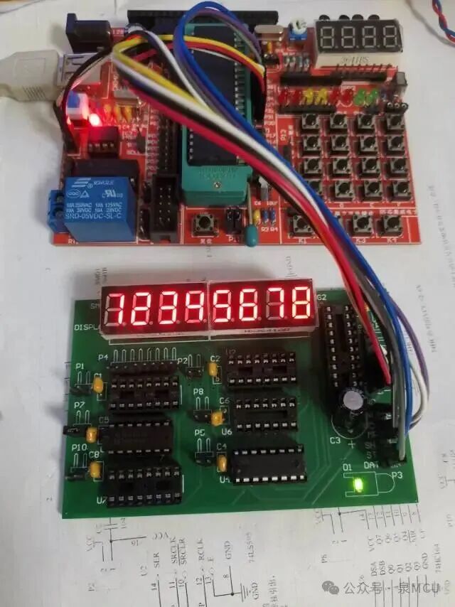 This is a photo taken online, showing that the display of 12345678 has a poor effect. It may be improved by making adjustments on the 74HC138.