
Abstract:Robotic arms are widely used in the industrial field, with grasping and placing being a common task. To promote the development of numerous industrial tasks, especially in laboratory environments, it is essential to quickly build robotic arm prototypes. This study aims to design a small three-degree-of-freedom robotic arm for grasping and placing tasks using inverse kinematics methods. The robotic arm system is designed using Solidworks software, employing four servo motors as driving devices, and using Arduino Mega 2560 as the microcontroller, embedding the inverse kinematics algorithm within it. This algorithm controls the movement of the robotic arm based on the target grasping and placing coordinates. Test results show that the robotic arm can complete grasping and placing tasks according to the given target coordinates, with a maximum average error of about 5 cm, and the error between the calculated results and the actual operation results is about 3%.
Original Authors: Adnan Rafi Al Tahtawi, Muhammad Agni, Trisiani Dewi HendrawatiEditor: AutoGo

01
Introduction
A robotic arm is a type of robot used in various industrial processes, capable of moving from one point to another by determining coordinate positions. The control of such robots can be manual or automatic; they can be used statically or operate while in motion. Inverse kinematics is a commonly used algorithm in robotic arm operations, which can convert coordinates into angular movements of the robot’s joints. Various methods can be employed to solve inverse kinematics problems, such as the Denavit-Hartenberg (D-H) method, screw theory, and iterative methods. Additionally, soft computing methods can also be used to solve inverse kinematics equations. Essentially, these methods aim to find the optimal solution for calculating joint angles based on target coordinates. Many researchers have explored the application of inverse kinematics in robotic arms, with one study using this method to control the movement position of the robotic arm during grasping and placing tasks. Other researchers have applied it in conveyor systems, object shape sorting, computer vision integration, and rapid prototyping. However, to facilitate the development of robotic arms, especially in studying their kinematics, a small robotic arm prototype is needed.
Some researchers have also developed low-cost small robotic arm prototypes. The study discussed the manufacturing process of lightweight robotic arm components, which took 6 to 10 hours. Each component of the robotic arm was designed through 3D simulation and produced as hardware using 3D printing technology. The results showed that the robotic arm met standards in terms of raw materials, metal reinforcement, accessibility, and flexible connections. A low-cost robotic arm with a balancing mechanism was developed, which helps balance the robotic arm during task execution, effectively reducing the motion torque of the robotic arm, allowing for the use of relatively inexpensive motor components. One study proposed a flexible robotic arm for grasping and placing tasks, which uses two DC motors and a silicone rod as flexible connecting components. Test results showed that this robotic arm could carry objects weighing more than twice its own weight. Other studies have designed low-cost robotic arms with recognition functions, such as using voice recognition methods to control the robotic arm. Furthermore, visual tracking and gesture control methods have also been integrated into robotic arms. Currently, with the rise of Internet of Things (IoT) technology, research on robotic arms is continuously evolving. For instance, a study developed an internet-connected robotic arm that can be operated via the internet. Given the development of IoT technology in the industrial field, such systems have significant application value. Finally, robotic arms have also been combined with drone (UAV) technology to form unmanned aerial manipulators (UAM).
This study aims to design a small robotic arm suitable for laboratory learning needs. The main contribution of this paper is to provide a simple robotic arm design scheme that can be used for small-scale research on robot behavior and tasks. The robotic arm is designed using Solidworks software and then produced using 3D printing technology. The robotic arm uses low-cost components, such as MG series servo motors and Arduino microcontrollers. In this study, based on the principles of inverse kinematics, automatic grasping and placing tasks are set for the robotic arm. This paper applies the inverse kinematics method to the robot and tests its automatic grasping and placing tasks.
02
Research Method
(1) System Design
The block diagram of the system design is shown in Figure 1. The system consists of an input part, a control part, and an output part. In the input part, there is a MATLAB graphical user interface (GUI) and an Arduino integrated development environment (IDE), which determine the coordinates of the robotic arm’s movement, including grasping and placing coordinates. The control part of the robotic arm is the Arduino Mega 2560, which embeds the inverse kinematics algorithm. In the output part, a 180-degree servo motor is used as the actuator. Table 1 shows the technical specifications of the designed robotic arm.
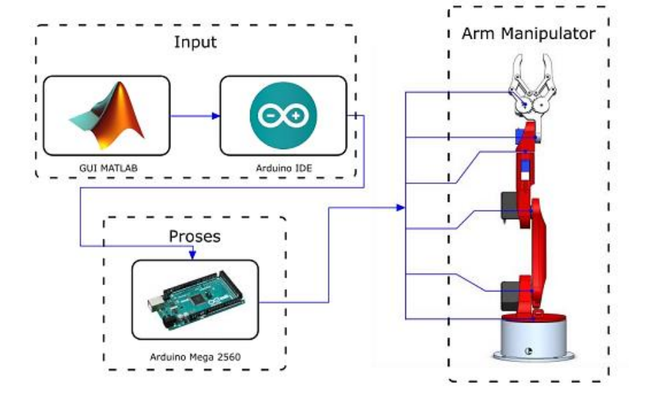
Figure 1. Robotic Arm System Design
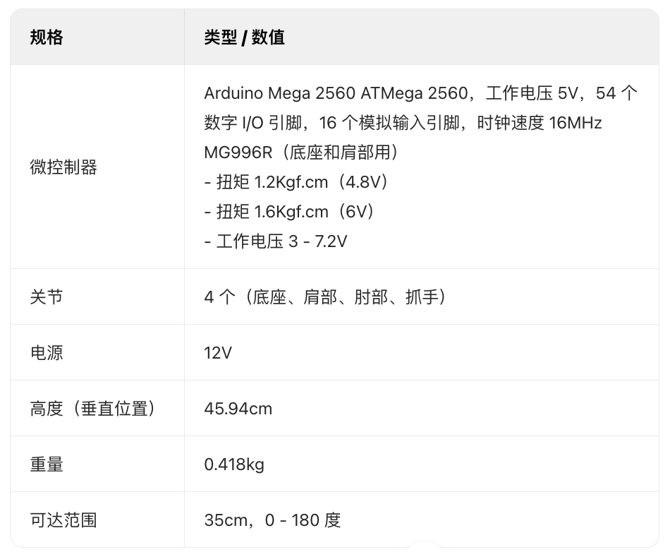
Table 1. Robot Parameters
(2) Hardware Design
The hardware design of the robotic arm includes mechanical and electronic components. The robotic arm system is designed to have three degrees of freedom, using a joint structure that includes three rotating joints and an end effector. The mechanical system of the robotic arm significantly impacts the entire system, as its shape and movement directly affect the tasks performed. The materials used to make the robotic arm are 3D printed polylactic acid (PLA) filament, made from corn starch. The material’s fill density is 5%, meaning the fill thickness of the manufacturing material is larger, making it lighter compared to materials with a fill density of 100% (where the fill thickness is tight and has no voids). Using a lower fill density allows the servo motor-driven joint movement system to be lighter, requiring less power during operation, as the weight differences of the component links affect the motion performance of the servo motors. Figure 2 shows the overall shape of the 3D model designed using Solidworks 3D modeling software. The three-degree-of-freedom robotic arm has four joints and link structures, namely the base, shoulder, elbow, and gripper. The movement of each joint is controlled by a servo motor, with the MG996R type servo motor used for the base and shoulder joints, and the SG90 type servo motor used for the elbow and gripper joints. Figure 3 shows a schematic diagram of the designed robotic arm. The four servo motor units are connected to the microcontroller, with three motors driving joint movements and one servo motor driving the gripper. The four servo motors are controlled using the “servo.write(degrees)” command, where “degrees” is the angle data generated by the inverse kinematics calculations. A 9V power supply is also added for the servo motors in the circuit, a 5V voltage regulator is provided for the microcontroller, and several LEDs are set as indicators.
Figure 2. Robot Hardware Design
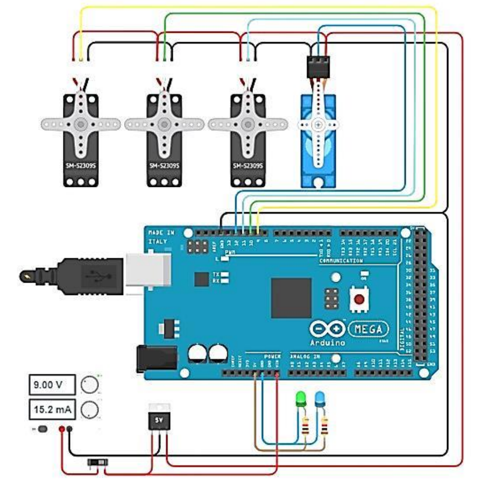
Figure 3. Electrical Schematic Design
(3) Software Design
The designed system is equipped with software based on MATLAB GUI as the interface, which is used to input the grasping and placing coordinates of the workpiece, as shown in Figure 4. The coordinates entered on the interface are sent to the Arduino Mega 2560 via serial communication, and then the inverse kinematics algorithm processes these coordinates to generate the angle values for each servo motor. Finally, the angle values are sent to each motor, allowing the robotic arm to move to the grasping and placing coordinate positions.
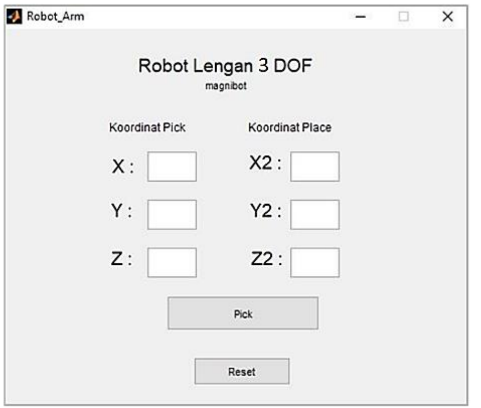
Figure 4. Robot Control Interface
The flowchart of the robotic arm operation process is shown in Figure 5. Generally, the workflow of the system starts with inputting the grasping and placing coordinates through the MATLAB GUI. After the coordinates are sent to the Arduino Mega 2560, they are processed through inverse kinematics calculations. The calculation results are the angle values for the base, shoulder, and elbow joints of the robotic arm. Once the angle values are obtained, they are sent to the servo motors of the robotic arm’s joints, allowing the end effector to reach the target point, and the gripper of the robotic arm can grasp and place objects at the specified coordinate positions.
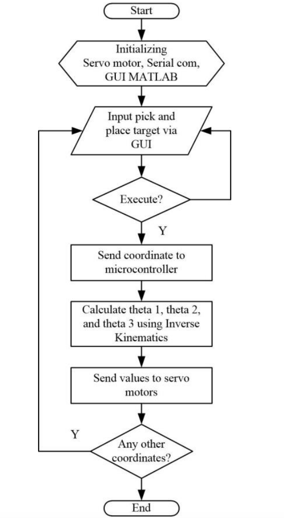
Figure 5. Robot Task Flowchart
(4) Inverse Kinematics
Inverse kinematics is a method for solving the joint angle variables of a robot based on the position coordinates of the robot. The inverse kinematics method aims to find the parameter values required for each actuator to achieve the final target coordinates. The block diagram of inverse kinematics is shown in Figure 6. When determining the final coordinates of the end effector, inverse kinematics must be adjusted in conjunction with the boundary conditions of the robot’s reachable workspace. Inverse kinematics problems can be solved using the Pythagorean theorem and trigonometric rules. By observing two views of the robot, namely the top view and the side view, the inverse kinematics problem can be solved. The top view is used to determine the angle θ1 of the base joint and the vertical rotation axis joint, while the side view is used to determine the angles θ2 of the shoulder joint and θ3 of the elbow joint. For the angle of the gripper, a switch algorithm can be used. The schematic diagrams of the robot’s top view and side view are shown in Figures 7 and 8, respectively.
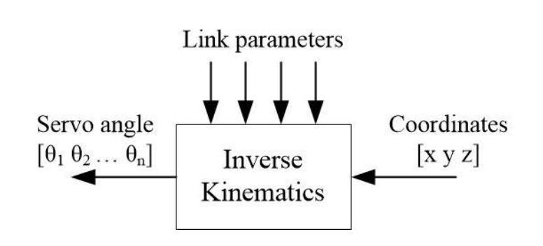
Figure 6. Inverse Kinematics Mechanism
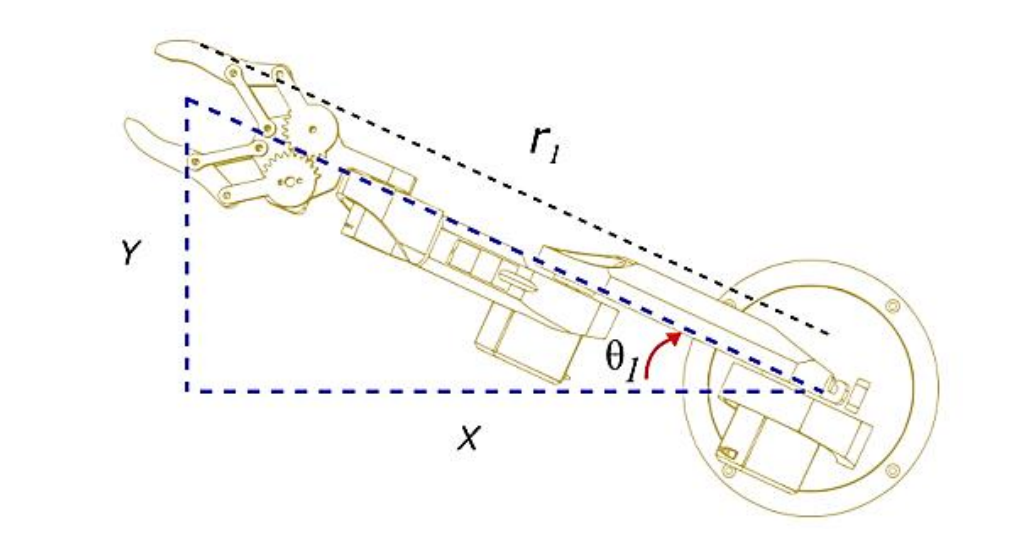
Figure 7. Robot Top View
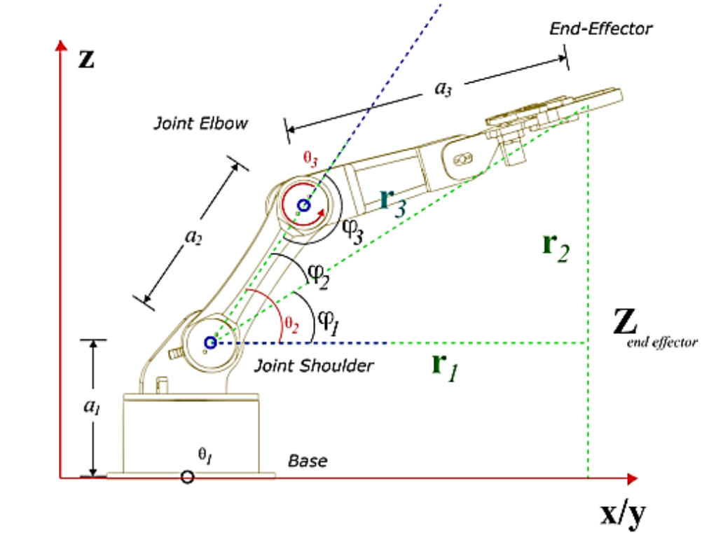
Figure 8. Robot Side View
To determine the angle of the base joint axis, the following tangent equation can be used:
Where Xef is the coordinate position of the end effector on the X-axis, Yef is the coordinate position of the end effector on the Y-axis, and θ1 is the angle of the base joint.
To find the angle θ2, a triangle auxiliary line is needed, which describes the lengths r1, r2, and r3 as shown by the green dashed line in Figure 7. Therefore, r1, r2, and r3 can be calculated using the following equations:
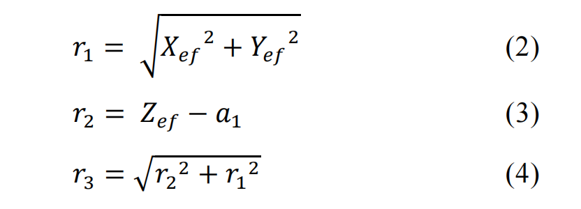
Where Zef is the coordinate position of the end effector on the Z-axis, and a1 is the length of the link between the base and shoulder.
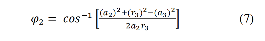
Additionally, by observing the side view of the three-degree-of-freedom robotic arm structure, the values of angles θ2 and θ3 can be obtained. From the side view, several variables can be defined, including a1, a2, a3, Zef, θ2, and θ3. a2 is the length of the link between the shoulder and elbow, and a3 is the length of the link between the elbow and the end effector. θ2 is the angle formed by the horizontal axis of the shoulder joint and the link between the shoulder and elbow, while θ3 is the angle formed by the horizontal axis of the shoulder joint and the elbow joint.
Referring to Figure 7, θ2 can be calculated using the following equation:
Where:

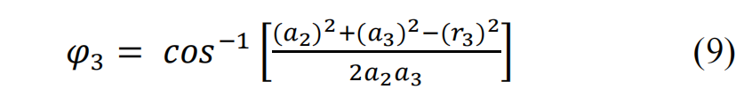
Meanwhile, θ3 can be calculated using the following equation:
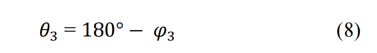
Where:
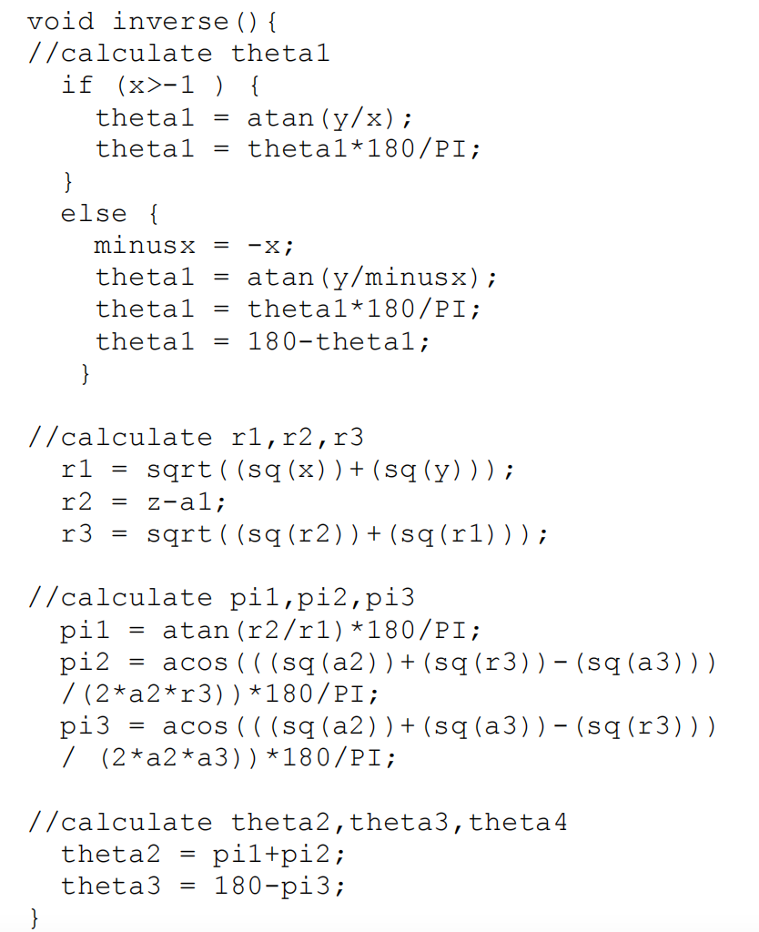
Then, the inverse kinematics equations are embedded into the microcontroller of the Arduino development board using a programming language. The following is a list of the inverse kinematics program written in C language in the Arduino IDE compiler:
03
Results and Discussion
According to the system block diagram shown in Figure 9, the overall system design is implemented. The constructed system is tested to evaluate its performance. The test content includes servo motor performance testing and grasping and placing task testing based on inverse kinematics.
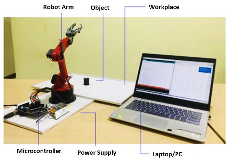
Figure 9. System Implementation
(1) Servo Motor Testing
The purpose of the servo motor testing is to determine whether the motors are functioning properly. The tests are conducted on the servo motors of each joint by measuring the voltage when PWM signals are sent to the servo motors and when no PWM signals are sent. The no-load voltage (VNL) refers to the voltage when the servo motor does not receive a PWM signal, while the full-load voltage (VFL) refers to the voltage when the servo motor receives a PWM signal and generates a load. The test results of the servo motors are shown in Table 2.
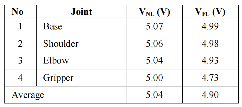
Table 2. Servo Motor Testing
From the test results, it can be seen that the average difference between the no-load voltage and the full-load voltage is 0.08V. This is due to power loss during the operation of the servo motors, which can affect the positional accuracy of the end effector.
(2) Grasping and Placing Coordinate Testing
This test aims to determine the ability of the end effector of the robotic arm to reach the target coordinates. During the test, the workspace is divided into two quadrants, with quadrant 1 corresponding to the area where the end effector’s X coordinate is negative, and quadrant 2 corresponding to the area where the end effector’s X coordinate is positive. By using a coordinate board and ruler for measurement, the differences between the target coordinates and the actual reached coordinates are obtained. The grasping coordinate test results are shown in Figure 10, and the placing coordinate test results are shown in Figure 11.
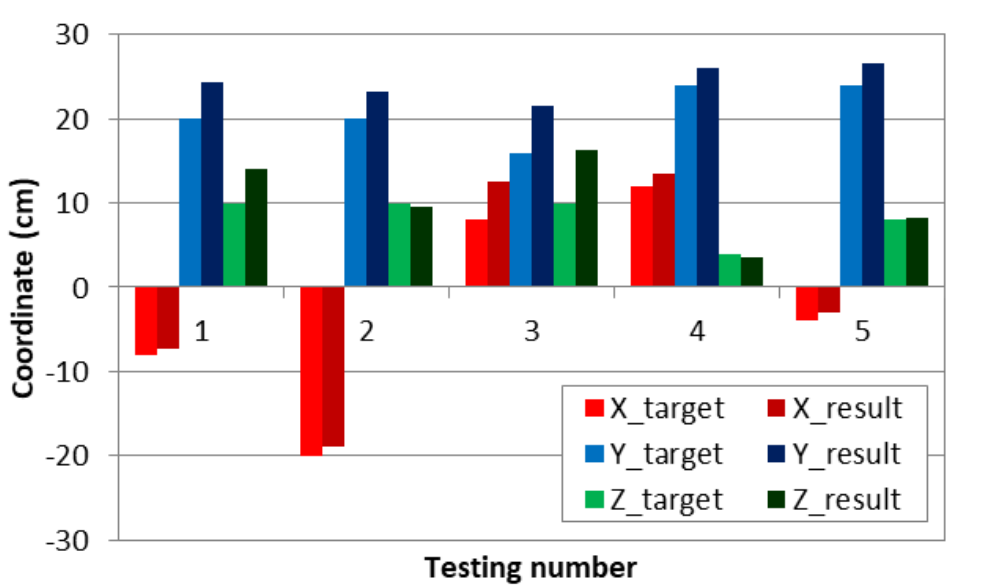
Figure 10. Grasping Coordinate Test Results
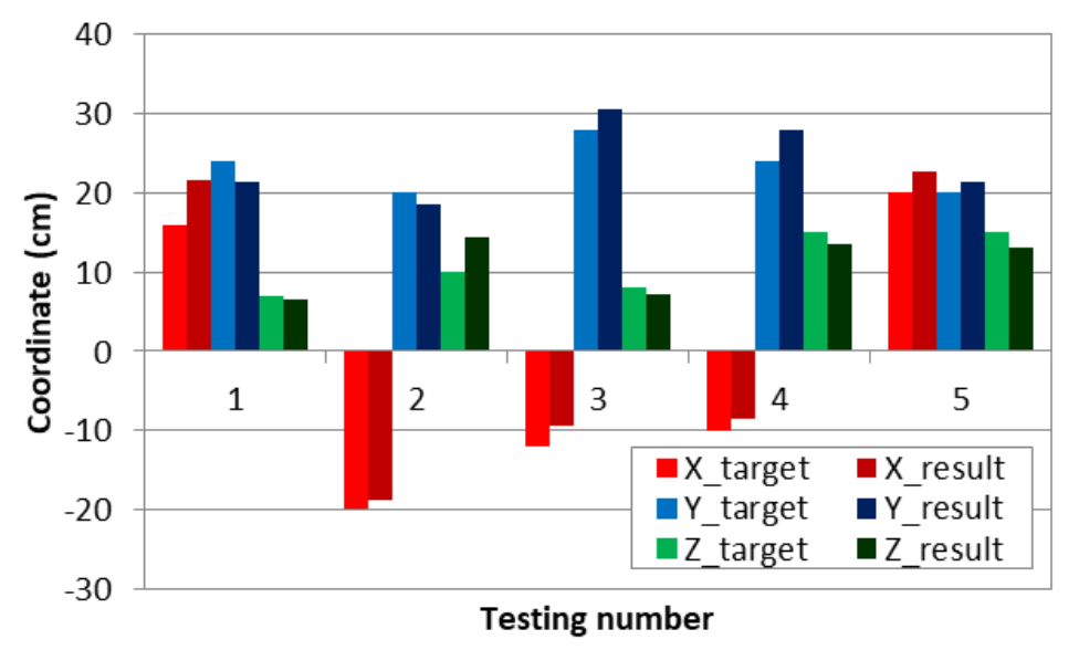
Figure 11. Placing Coordinate Test Results
According to the grasping coordinate test results, despite the errors, the robotic arm is able to reach the given target coordinates. The maximum average error occurs on the Y-axis, reaching 3.5 cm, while the minimum average error occurs on the X-axis, reaching 1.74 cm. From the testing process, the third test had the maximum average error of 5.4 cm, while the fifth test had the minimum average error of 1.27 cm.
In the placing coordinate test, it can also be observed that the robotic arm is able to reach the target coordinates, but there are also errors. The maximum average error occurs on the X-axis, reaching 2.68 cm, while the minimum average error occurs on the Z-axis, reaching 1.78 cm. In the tests, the first test had the maximum average error of 2.87 cm, while the third test had the minimum average error of 1.93 cm.
(3) Servo Angle Testing Based on Inverse Kinematics
The purpose of the servo angle testing is to determine the angle values generated by the microcontroller’s calculations and compare them with the results calculated manually using Ms. Excel. The tests are conducted by providing five test coordinates (x, y, z) under grasping and placing conditions. The test coordinates under grasping conditions are (-8, 20, 10), (-20, 20, 10), (8, 16, 10), (12, 24, 4), and (-4, 24, 8), while the test coordinates under placing conditions are (16, 24, 7), (-20, 20, 10), (-12, 28, 8), (-20, 24, 15), and (20, 20, 15). Then, the calculated results of angles θ1, θ2, and θ3 are displayed on the Arduino IDE serial monitor. At the same time, the servo angles calculated by the Arduino microcontroller are compared with the angles calculated based on the inverse kinematics equations, and the error is calculated using the following error formula:

Tables 3 and 4 show the angles generated by inverse kinematics for each servo motor under grasping and placing conditions, respectively. According to the test data, it was found that two angles exceeded the maximum limit of 180 degrees, specifically the angle θ3 during the first test under grasping conditions (192.02°) and the angle θ3 during the third test (209.61°). When this occurs, the motion of the servo motor will saturate at 180°, which may lead to errors in the grasping coordinates.
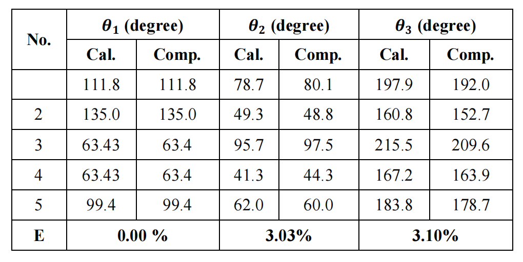
Table 3. Servo Angles During Grasping
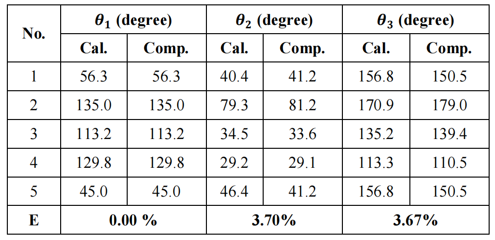
Table 4. Servo Angles During Placing
The test results indicate that during grasping and placing operations, there is an approximate 3% error between the calculated angles generated and the actual calculated angles for θ2 and θ3. The calculated result for angle θ1 matches the calculated result. This is because the equation for θ1 is relatively simple compared to the equations for θ2 and θ3. The error may be due to differences in data type resolution during the calculation process.
This study applied the inverse kinematics method to design a small robotic arm for grasping and placing tasks. In this study, the general equations were still used to solve inverse kinematics. Various methods for solving inverse kinematics have been developed, such as the Denavit-Hartenberg (D-H) method, screw theory, and iterative methods. Each of these three methods has its advantages and disadvantages; in terms of computation time, the D-H method is the fastest, while the iterative method takes the longest. However, the choice of inverse kinematics solving method can be adjusted based on the specifications and tasks of the designed robot.
04
Conclusion
A small robotic arm capable of grasping and placing tasks based on inverse kinematics has been successfully designed, implemented, and tested. The applied inverse kinematics method enables the robot to perform grasping and placing tasks for multiple target coordinates. The test results show that in the third grasping test, the maximum average coordinate error reached 5.4 cm. The maximum average error between the calculated and actual servo angles was 3.7%. This was caused by the saturation phenomenon of the servo motors and differences in data type resolution. Future research will consider the saturation of actuators and design closed-loop control algorithms.
Disclaimer: The views expressed in this article are for sharing and communication purposes only. The copyright and interpretation rights belong to the original authors and publishing units. If there are any copyright issues, please contact [email protected], and we will address them promptly.
Related Articles ·
▷ TOP 5 List: Five Major Generative AI Tools for 2025
▷ Infineon Vice President: Three Key Features to Bring Edge AI Mainstream by 2025
▷ The World’s First Bidirectional Adaptive Brain-Computer Interface Developed Successfully by a Chinese Team!
▷ Hardware Design of Bipedal Humanoid Robots: A Technical Overview
▷ Mechanical Principles of Humanoid Robots
▷ Methods of Interaction Between Robots and Humans and Multimodal Interface Architecture
▷ AI-Based Human-Machine Collaborative Unit Task and Action Planning Methods
▷ The Humanoid Robot Market is Expected to Reach $76.97 Billion by 2032, with a Compound Annual Growth Rate of 48.36%