The “2022 Smart Power Plant Industry Insight White Paper” covers an overview of recent developments in the smart power plant sector, data analysis, and hundreds of smart construction projects by power generation companies. Additionally, the section on smart power plant construction solutions invites industry experts to elaborate on the overall construction roadmap for the digital transformation of power generation, as well as cutting-edge research results and application solutions involving foundational support, intelligent power generation, intelligent safety, energy conservation and environmental protection, intelligent equipment, and innovative applications of information technology.
It delves into technological innovations in foundational areas such as digital infrastructure as computational support, cloud computing and cloud-edge collaboration, big data and artificial intelligence platforms, and next-generation 5G communication technology, extending to specific application scenarios in power production such as intelligent control, intelligent monitoring, intelligent fuel management, intelligent inspection, and intelligent monitoring.
Intelligent Control – Intelligent Control Technology and Applications for Thermal Power Units
With the advancement of the national “dual carbon” strategy and the promotion of “smart power plant” construction, how thermal power units can reduce coal consumption for power supply, enhance flexible adjustment capabilities, and improve clean and efficient levels has become a critical question.
Shanghai Xinhua Control Technology Group Co., Ltd. (hereinafter referred to as Xinhua Technology) has independently developed the iFOC (Intelligent Feedback-based Optimized Control) intelligent control technology based on the ICS (Intelligent Control System) architecture, aimed at the operational needs of units. This technology combines traditional PID control with intelligent control, characterized by “static balance, feedback correction, parallel feedforward, and dynamic acceleration.” Through statistical learning and system identification, it obtains intelligent multimodal object models, supplemented by online model correction technology, automatic online calculation/assignment of control parameters, and adaptive technology for estimating state variables. It is currently being promoted in large thermal power units to help achieve cost reduction, efficiency enhancement, energy conservation, emission reduction, and intelligent upgrades.
1. iFOC Intelligent Control System
1. iFOC Intelligent Control Architecture
The application architecture of the iFOC intelligent control system is shown in Figure 1. When applied to the Xinhua series DCS system, only one pair of redundant high-performance optimized dedicated controllers needs to be added, and all optimization calculations are performed within the dedicated controllers. Its features include: eliminating “external attachments” and “black boxes,” seamless integration with the DCS system, high reliability, maintainability, and openness, as well as high communication speed with refresh cycles identical to the DCS system.
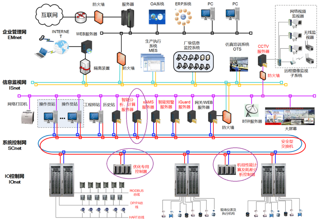
Figure 1: Application Architecture of the Intelligent Control System on the Xinhua DCS Platform
The iFOC intelligent control system can also be applied in non-Xinhua series DCS systems. By configuring redundant high-performance optimized dedicated controllers and Xinhua DCS configuration software, it has been successfully applied in ABB, Emerson, and Siemens DCS systems.
2. iFOC Intelligent Control Software Package
The iFOC intelligent control software package is developed based on Xinhua Technology’s mature and user-friendly iCAN software platform, seamlessly integrated, and adopts a WYSIWYG graphical configuration (as shown in Figure 2), making it completely transparent to users, easy to configure, maintain, and strong in analysis. The 62 dedicated optimization control modules of iFOC cover intelligent coordination, intelligent steam temperature, intelligent denitrification, and intelligent soot blowing scenarios for thermal power units.
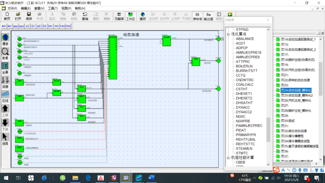
Figure 2: iFOC Intelligent Control Configuration and Optimization Module Library
3. iFOC Performance Indicators
Under optimal equipment conditions, within a load range of 40% to 50%, the iFOC intelligent control system can achieve the assessment indicators shown in the table below.
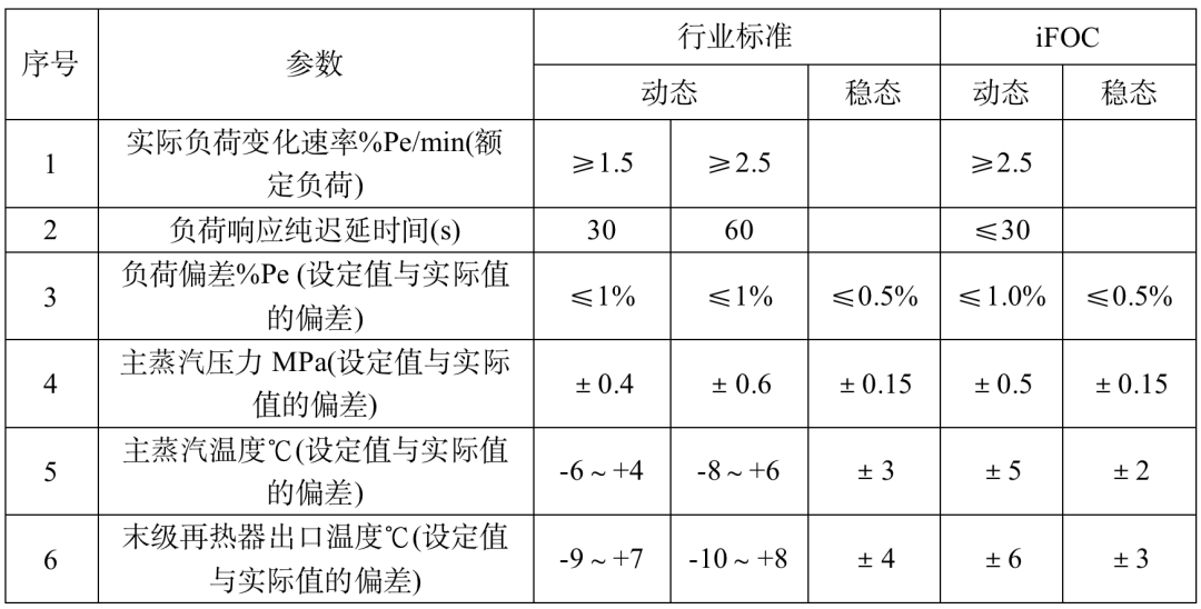
Note: The indicators from the “DL/T 1492.2-2016 Technical Guidelines for Optimization Control Systems in Thermal Power Plants” do not include the operational states of mill start/stop and soot blowing, while the iFOC indicators include these operational states.
2. iFOC Intelligent Coordination Technology
1. Technical Route
Xinhua Technology’s iFOC intelligent coordination control achieves optimization functions such as coordination between the thermal power unit and boiler, primary frequency modulation, and deep peak shaving, and has achieved excellent operational results in various types of units ranging from 135MW to 1000MW.
The main advanced control technologies applied include: ① Model-based multivariable advanced control technology; ② Artificial intelligence dynamic acceleration technology; ③ State variable estimation-based adaptive technology; ④ Gain scheduling technology; ⑤ Dynamic acceleration output suppression technology under continuous reverse AGC commands; ⑥ Multimodal, multi-objective, multi-constraint, variable structure optimization control; ⑦ Pressure setpoint prediction during sliding pressure variable load processes; ⑧ Support for step load commands with a load variation range of 50% Pe, supporting AGC-R mode technology; ⑨ Variable parameter (VAPID) PID control; ⑩ Variable load rate optimization; ⑪ Dynamic decoupling self-correction function for steam turbine control valve, overheating cooling water flow, and front pressure; ⑫ Compensation control for primary frequency modulation; ⑬ Coordinated control strategy for primary air manifold pressure and capacity air door in combustion control; ⑭ Condensate throttling technology; ⑮ Flexibility scheduling technology. A brief introduction is as follows:
● Model-based Multivariable Advanced Control Technology
Model-based multivariable advanced control (Model Predictive Control, MPC) is an advanced control technology commonly used in industrial automation and process control. It establishes a dynamic mathematical model to describe the control system and uses this model to predict future system behavior and responses. The controller adjusts not only based on the current state but also considers the dynamic behavior over a future period, optimizing current control decisions through future predictions to achieve better control outcomes.
● Artificial Intelligence Dynamic Acceleration Technology
Since the production in thermal power plants is a fast/slow alternating controlled process, it is necessary to achieve dynamic balance between energy in the boiler and turbine while meeting grid load demands. This leads to the development of dynamic acceleration technology, which quickly responds to load changes, improving the response speed and stability of thermal power plants. Artificial intelligence dynamic acceleration technology refers to the real-time adjustment of computational resource allocation during training or inference to enhance the operational efficiency and speed of the AI system.
● State Variable Estimation-based Adaptive Technology
State variable estimation-based adaptive technology is a control algorithm that can adaptively adjust control parameters by real-time estimating and correcting the system’s state variables to meet control requirements. It enables refined control of complex systems, exhibiting good adaptability and robustness. To meet the wide load variation demands of 30% Pe to 100% Pe AGC, load command control quality assurance has been achieved under rate changes of 0.8% Pe/min to 2.5% Pe/min using state variable estimation technology.
● Gain Scheduling Function
Gain scheduling technology is commonly used in control systems to adaptively adjust the system’s gain parameters for better control effects and stability. It is typically applicable to nonlinear systems, where the system’s performance and stability often depend on the current operating point. The Xinhua Technology iFOC gain scheduling function corrects control variables based on main steam pressure deviations, expanding the load step disturbance range from 10% Pe to 15% Pe to 50% Pe under control index constraints, thereby increasing the system’s variable load adaptability.
● Dynamic Acceleration Output Suppression Technology under Continuous Reverse AGC Commands
This technology refers to controlling and suppressing the dynamic acceleration process of the unit in the AGC system of thermal power plants when small continuous reverse changes occur in AGC commands, to avoid issues such as overload and overfrequency.
● Multimodal, Multi-objective, Multi-constraint, Variable Structure Optimization Control
This is a high-level control algorithm that integrates various control technologies to achieve efficient, stable, and reliable control in complex systems.
● Pressure Setpoint Prediction Function during Sliding Pressure Variable Load Processes
This function predicts the corresponding pressure setpoint during the low and high load changes of sliding pressure units by establishing pressure setpoint models, state estimation and prediction, and control strategy design, achieving precise control and optimized operation of sliding pressure units. The trend prediction of actual setpoint changes under the target pressure setpoint is an effective means to improve the control quality of the boiler’s main control under sliding pressure operation, reducing the deviation of main steam pressure by approximately 0.2MPa compared to before.
● Support for AGC-R Mode Technology
AGC-R mode is a newer automatic generation control (AGC) mode, further optimized and improved based on traditional AGC modes. Compared to traditional AGC modes, AGC-R mode is more suitable for the operational management and optimization of power systems. Supporting AGC-R mode requires certain hardware and software conditions, such as advanced AGC controllers, real-time data acquisition and processing systems, and highly reliable communication networks.
● Variable Parameter (VAPID) PID Control
Variable parameter (VAPID) PID control is an adaptive control method used to address complex issues such as variable parameters and nonlinearity in control systems. The VAPID controller monitors and estimates parameter changes in real-time and adjusts the gain parameters in the PID controller accordingly to achieve better control effects and stability.
● Variable Load Rate Optimization
This refers to optimizing the output change rate of generating units based on real-time load demand changes during coordinated control, ensuring the system’s speed, stability, and reliability.
● Decoupling Control of Steam Turbine Control Valve, Overheating Cooling Water Flow, and Front Pressure
This is a multivariable control strategy applied in steam turbine regulation systems. The strategy reduces coupling interference in the steam turbine system through decoupling processing, improving control accuracy and stability. By employing a multivariable controller based on state space models, utilizing model predictive control and decoupling technology, the coupling relationships among the control variables of steam turbine control valve opening, overheating cooling water flow, and front pressure are separated, allowing each control variable’s control process to be independent, thus optimizing control outcomes.
● Compensation Control for Primary Frequency Modulation
In power systems, power quality issues have always been significant. Primary frequency modulation adaptive compensation technology is an effective solution that can improve power quality by using adjustable compensation devices at the power source. However, traditional primary frequency modulation technology typically requires fixed parameter adjustments, making it difficult to adapt to different load conditions, which limits its applicability. Especially during small slip, due to dead zones and stickiness in the control valve, the accuracy of primary frequency modulation may decrease. To address this issue, a strong adaptive primary frequency modulation compensation method based on intelligent time windows is adopted. This method uses intelligent time windows to calculate the dynamic response of loads and employs adaptive algorithms to readjust the parameters of the compensation device for more precise compensation. This method can quickly adapt to load changes and fluctuations in power signals, thereby improving the power quality and reliability of the power source.
● Condensate Throttling Technology
Condensate throttling technology can be applied in primary frequency modulation and AGC to achieve more efficient and reliable power generation scheduling. In primary frequency modulation, condensate throttling technology can reduce the flow of condensate, decreasing the thermal load on the boiler, thus achieving power control of the generating unit. Specifically, when the generating load increases, condensate throttling technology can adjust the flow and pressure of condensate to reduce the thermal load on the boiler, ensuring that the output power of the generating unit meets the requirements. When the generating load decreases, condensate throttling technology can correspondingly adjust the flow and pressure of condensate to avoid excessive condensate production, improving energy-saving effects. In AGC, condensate throttling technology can control the flow and pressure of condensate pumps to adjust the frequency and power of the generating unit. When the system load changes, condensate throttling technology can quickly adjust the flow and pressure of condensate pumps to control the output power of the generating unit, ensuring the stability of system frequency and power.
2. Application Cases
Case 1:
A certain 330MW subcritical unit (Figure 3) had an original boiler main control output variation range of ±18%. After adopting intelligent coordination technologies such as artificial intelligence dynamic acceleration and AGC-R mode adaptation, the variation range was reduced to ±3%, improving adjustment quality while reducing unit coal consumption and extending equipment life.
Figure 3: Application Case of a 330MW Subcritical Unit
Case 2:
With the large-scale integration of new energy into the grid, ensuring control quality while load variation ranges from 10% Pe to 15% Pe to 50% Pe is a challenge faced by the industry.
A certain 300MW subcritical unit (Figure 4) adopted intelligent coordination technologies such as gain scheduling, and the load dropped from 300MW to 150MW continuously, then directly increased from 150MW to 300MW, with a load variation rate of 2% Pe/min; the process included mill start/stop, with a maximum pressure deviation of 0.46MPa (less than the 0.51MPa indicator) and a maximum power deviation of 1.75MW (less than the 3MW indicator).
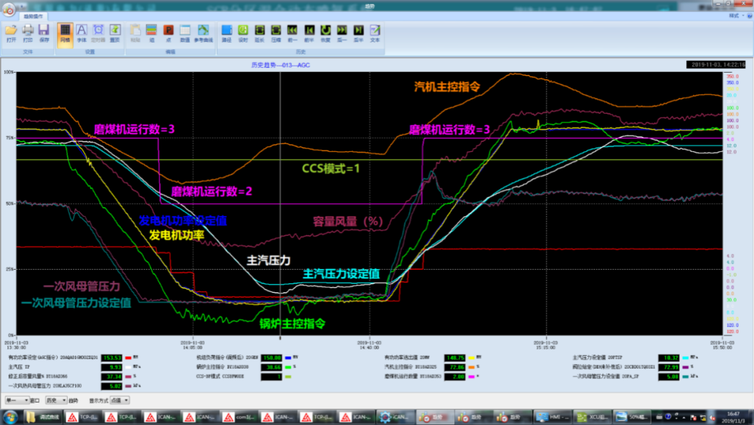
Figure 4: Application Case of a 300MW Subcritical Unit
Case 3:
A certain 600MW subcritical unit (Figure 5) faced significant steam pressure losses and long constant pressure sections (240MW: 11.08MPa → 420MW: 16.3MPa → 600MW: 16.3MPa), with regulations requiring a maximum front pressure of 16.9MPa under normal operating conditions (including mill start/stop). The original control method frequently exceeded pressure limits, making optimization difficult. After adopting intelligent coordination technologies based on multimodal, multi-objective, multi-constraint, and variable structure, since its commissioning in 2018, the maximum front pressure has only reached 16.81MPa, with no records of exceeding pressure.
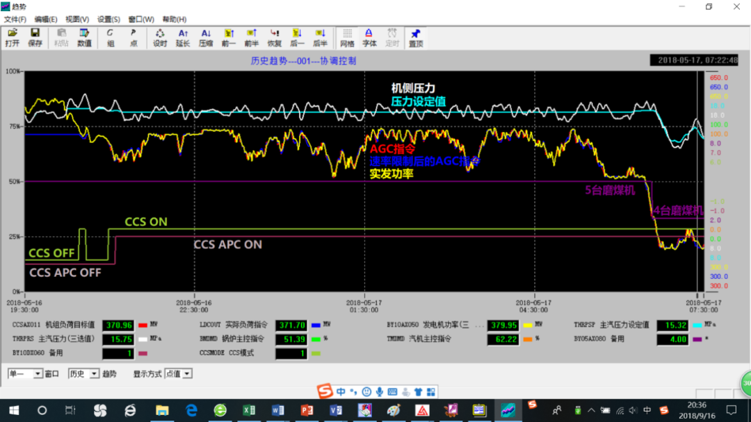
Figure 5: Application Case of a 600MW Subcritical Unit
Case 4:
A certain 660MW supercritical unit (Figure 6) adopted intelligent coordination technology based on state variable estimation, and the control quality is shown in Figure 6. The iFOC intelligent coordination system can automatically adapt to different actual load command rate changes, achieving a maximum deviation of only ±0.47MPa between the main steam pressure and setpoint, greatly improving control quality.
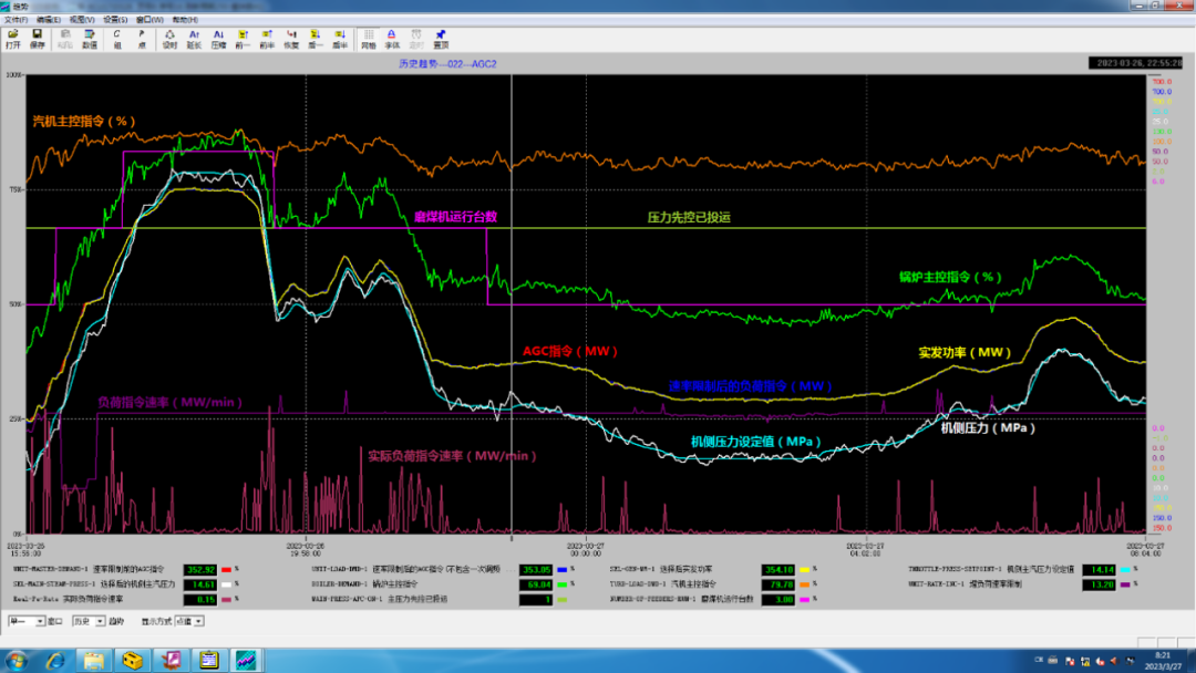
Figure 6: Application Case of a 660MW Supercritical Unit
3. Application Summary
The gain scheduling of control variables, state variable estimation, and pressure setpoint prediction are specific applications of adaptive control and self-organizing control concepts in iFOC intelligent coordination. By applying iFOC intelligent coordination technology, the unit’s load command rate can vary from 0.5% Pe/min to 2.5% Pe/min, and the amplitude of load disturbances has been expanded from the industry standard of 10% Pe to 15% Pe to 50% Pe, while ensuring that the main steam pressure is controlled within a deviation range of 3% P0, outperforming industry standards. After applying iFOC intelligent coordination technology, the unit has improved its Kp value, enhancing its response characteristics to the grid, potentially reducing grid assessment and even generating revenue; at the same time, it has improved boiler combustion control performance and reduced coal consumption for power supply.
3. iFOC Intelligent Steam Temperature Technology
1. Technical Route
Steam temperature control is crucial for the safe and efficient operation of units; however, due to various external disturbances, significant delays, inertia, and nonlinearity, the operational effects of most units are not ideal. In recent years, the iFOC intelligent steam temperature technology, based on the enthalpy increase characteristics of superheaters (reheaters), has been innovatively applied in steam temperature control for units ranging from 300MW to 1000MW, achieving excellent operational results.
The main advanced control technologies applied include: ① Advanced control based on the enthalpy increase characteristics and energy balance of superheaters (reheaters); ② Nonlinear model online automatic correction; ③ Dynamic decoupling self-correction control; ④ Variable parameter (VAPID) PID control; ⑤ Optimization control based on steam temperature rise rate; ⑥ Constraint technologies for preventing low temperature and wall temperature overheating; ⑦ Optimization control based on deviation; ⑧ Soft measurement of outlet temperature of the desuperheater; ⑨ Multi-step advanced steam temperature control technology based on disturbance prediction; ⑩ Anti-integral saturation technology with locking and tracking; ⑪ Optimization control based on valve characteristics.
● Intelligent Steam Temperature Control Strategy
The iFOC intelligent steam temperature control block diagram is shown in Figure 7. The main regulator receives output signals from the pre-processing module (STMTC) to achieve optimization control based on deviation, anti-integral saturation technology with locking and tracking, and variable parameter VAPID control for the main loop. The enthalpy increase model calculation module (QUAEQC) collaborates with the steam parameter calculation module (CSTHT) to achieve enthalpy increase model calculation, online correction, dynamic decoupling, and calculation of the inlet temperature of the superheater.
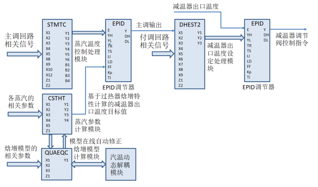
Figure 7: iFOC Intelligent Steam Temperature Optimization Control
● Enthalpy Increase Model Modeling
The iFOC intelligent steam temperature technology employs principal component analysis (PCA) driven by big data to integrate the enthalpy increase model. The load, burner swing angle (overheating and reheating temperature damper opening ratio), and the temperature at the superheater (reheater) have a corresponding relationship with the enthalpy increase, establishing the enthalpy increase model for the superheater (reheater).
● Online Model Correction
Online automatic model correction refers to the real-time monitoring and analysis of data and models in machine learning and artificial intelligence systems, continuously learning and providing feedback to automatically adjust and optimize the model to improve system performance and accuracy. The iFOC intelligent steam temperature technology employs nonlinear model online automatic correction functionality, effectively overcoming quality degradation in steam temperature control caused by model mismatches.
● Dynamic Decoupling Self-Correction Control
Dynamic decoupling self-correction control (DDSCC) is a new control method based on self-correction, decoupling, and dynamic control, used to address control issues in multivariable, nonlinear, and coupled complex systems. The main idea of DDSCC is to decompose the control system into multiple subsystems, allowing each subsystem to be controlled independently without interference from other subsystems. Additionally, DDSCC employs dynamic control methods to continuously adjust control parameters based on real-time feedback and monitoring information to adapt to system changes and uncertainties.
● Optimization Control Based on Steam Temperature Rise Rate
Optimization control based on steam temperature rise rate is a new control method applied in boiler outlet steam temperature control, focusing on optimizing adjustments based on the important control indicator of steam temperature rise rate to achieve stable operation and improve operational efficiency of the unit.
● Constraint Technologies for Preventing Low Temperature and Wall Temperature Overheating
The main purpose of the low temperature constraint technology is to ensure that the boiler outlet steam temperature does not drop too low. A low outlet steam temperature can lead to decreased boiler efficiency and safety issues. The main purpose of the wall temperature overheating constraint technology is to ensure that the wall temperature at the boiler outlet does not rise too high. Excessively high wall temperatures can cause damage and aging of boiler components, potentially leading to safety accidents. Preventing low temperature and wall temperature overheating are important constraints to consider in steam temperature control processes. By reasonably designing control system structures and parameters, employing advanced sensors and controllers, and utilizing high-precision control algorithms, these issues can be effectively addressed, ensuring safe operation and improving efficiency of the boiler.
● Error-Based Optimization Control (EBOC)
Error-Based Optimization Control (EBOC) is an optimization method based on error or deviation for control. Compared to traditional control methods, EBOC is more flexible, allowing for real-time adjustments based on system responses and control needs, thereby improving the performance and stability of the control system. The basic idea of the EBOC method is to introduce a control deviation variable into the control system, optimizing the changes in the control deviation variable to achieve optimized control of the system.
● Soft Measurement of Desuperheater Outlet Temperature
Soft measurement of desuperheater outlet temperature refers to a technique for estimating the outlet temperature of the desuperheater through mathematical modeling and computer algorithms. When traditional temperature measurements encounter issues, soft measurement technology for desuperheater outlet temperature can resolve control challenges.
● Multi-step Advanced Steam Temperature Control Technology Based on Disturbance Prediction
This advanced control method can achieve rapid and precise control of outlet steam temperature during boiler operations, providing strong support for safe and efficient boiler operation.
● Anti-integral Saturation Technology with Locking and Tracking
Integral terms are often used in control systems to eliminate steady-state errors, but when the input signal of the controlled object exceeds certain limits, the integral term can become saturated, leading to system instability. To address this issue, anti-integral saturation technology with locking and tracking has been proposed. This technology consists of two parts: locking and tracking. The locking part involves locking the integral term when the input signal exceeds certain limits, preventing it from participating in control. The tracking part addresses the inability to eliminate steady-state errors when the integral term is locked, potentially leading to further increases in steady-state errors as the outlet temperature of the cooling water continues to drop. To resolve this, a tracking term is introduced to eliminate steady-state errors through tracking. Anti-integral saturation technology can effectively solve saturation issues of integral terms and improve system stability and robustness. This technology is widely applied in control systems, especially those with integral terms, such as PID controllers.
● Optimization Control Based on Valve Characteristics (VCBOC)
Optimization Control Based on Valve Characteristics (VCBOC) is a control method that addresses the impact of valves on control system performance. This method optimizes the relationship between valve opening and control variables to enhance the response speed, stability, and robustness of the control system.
2. Application Cases
Case 1:
A certain 330MW subcritical unit (Figure 8) adopted intelligent optimization technologies based on flue gas temperature energy balance, resulting in a dynamic temperature deviation of only ±1.5℃.
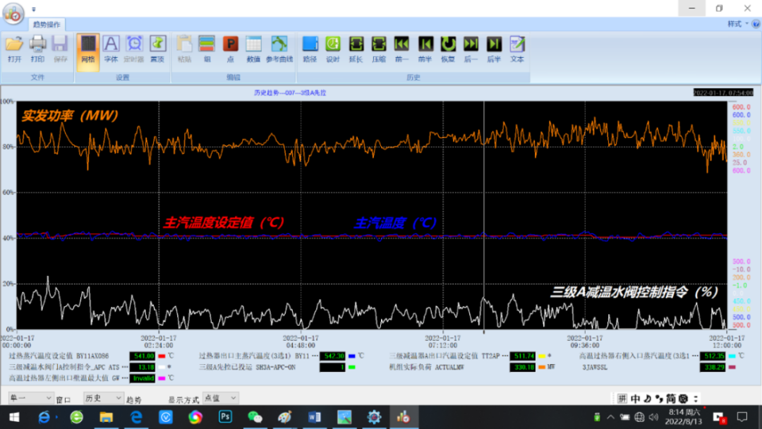
Figure 8: Application Case of a 330MW Subcritical Unit
Case 2:
A certain 350MW subcritical unit (Figure 9) adopted intelligent steam temperature technologies such as model prediction and adaptive control based on superheater enthalpy increase, achieving a deviation of ±3℃ during dynamic load changes; after completing left and right side balance control and online model correction, the deviation during dynamic conditions was only ±1.5℃; simultaneously, fluctuations in the control valve were significantly reduced, extending equipment lifespan.
Figure 9: Application Case of a 350MW Subcritical Unit
Case 3:
A certain 650MW supercritical unit (Figure 10) adopted intelligent optimization technologies such as model adaptive control, achieving control of overheating steam temperature within ±4.6℃ and reheating steam temperature within ±3℃ under continuous reverse load command rates of 2% Pe/min with a load variation amplitude of 10% Pe; subsequent optimization of the outlet enthalpy of the steam-water separator further improved control quality.
Figure 10: Application Case of a 650MW Supercritical Unit
Case 4:
A certain 1000MW ultra-supercritical unit (Figure 11) adopted iFOC intelligent steam temperature control technology, introducing online model self-correction and dynamic decoupling self-correction technologies, achieving control of overheating steam temperature within ±2.0℃ under variable load commands, and controlling overheating steam temperature within ±3.5℃ during load changes involving mill start/stop; subsequent optimization of the outlet enthalpy of the steam-water separator further improved control quality.
Figure 11: Application Case of a 1000MW Ultra-Supercritical Unit
3. Application Summary
As mentioned above, the iFOC intelligent steam temperature system utilizing intelligent optimization technology can achieve dynamic steam temperature control deviations of ±3℃ under conditions without mill start/stop and soot blowing operations; including conditions with mill start/stop and soot blowing operations, dynamic steam temperature control deviations can reach ±5℃; all indicators exceed industry standards.
For example, in a certain 600MW unit (with a coal consumption of 300g/kWh and a standard coal price of 1000¥/t), after adopting iFOC intelligent steam temperature technology, if the overheating steam temperature increases by 2℃ and the reheating steam temperature increases by 4℃, the unit’s coal consumption can decrease by 0.5g/kWh, saving approximately 1.6 million in coal costs annually.
4. iFOC Intelligent Denitrification Technology
1. Technical Route
With the gradual increase in environmental protection requirements in China, the progress of ultra-low emissions in thermal power has been rapid. Major coal-fired thermal power enterprises are constructing and renovating desulfurization, denitrification, and dust removal devices, with rapid development and gradually mature technology processes, but many issues still exist. The main problem is that SCR outlet NOx control has significant delays and inertia, and external disturbances (load, fuel, and air volume) affect SCR outlet NOx much faster than ammonia injection.
The iFOC intelligent denitrification technology mainly applies the following advanced control technologies: ① Multivariable control; ② Efficiency and concentration constraints; ③ Two control modes for outlet NOx concentration and denitrification efficiency; ④ Optimization control to meet the process requirements of urea thermal (hydrolysis) and direct ammonia injection; ⑤ Balancing control of left and right side outlet NOx concentration (efficiency); ⑥ Estimation of measurement values during backflushing; ⑦ Intelligent zoned ammonia injection optimization control.
● Ammonia Injection Feedforward
SCR outlet NOx control uses the ammonia injection amount calculated based on chemical reaction equations as the feedforward quantity for the control system, supplemented by various intelligent control technologies.
● Backflushing Estimation
By employing an estimation algorithm for measurement values during backflushing, disturbances to the control system caused by discrepancies between the maintained values and actual measurement values at the end of backflushing can be resolved. After employing the estimation function, the outlet NOx concentration varies with changes in operating conditions, avoiding disturbances introduced by backflushing.
● Balancing Control
Balancing control of left and right side outlet NOx concentration (efficiency) is aimed at overcoming the asymmetry of outlet NOx concentration (efficiency) on the left and right sides during production processes.
● Zoned Ammonia Injection
Intelligent zoned ammonia injection optimization control is used for precise ammonia injection applications.
2. Application Cases
Case 1:
Figure 12 shows a comparison of estimated and measured values of NOx concentration at the A side inlet of a certain unit’s SCR before and after backflushing. After adopting the iFOC intelligent denitrification measurement value estimation technology, disturbances to the control system during the purging process can be effectively resolved.
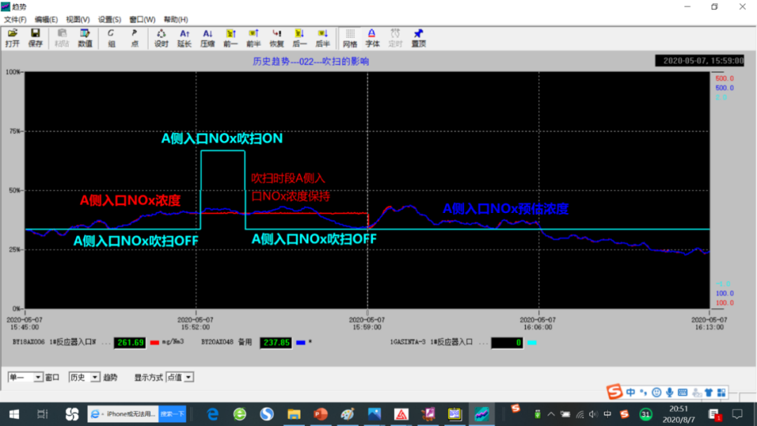
Figure 12: Application of NOx Concentration Backflushing Estimation in a Certain Unit
Case 2:
The zoned ammonia injection control process curve of a certain 330MW unit is shown in Figure 13. Due to changes in load commands and operating conditions, the NOx concentration in each zone at the outlet of reactors A and B is constantly changing. Through the intelligent zoned ammonia injection control system, deviations in NOx concentration in each zone are minimized, achieving precise ammonia injection.
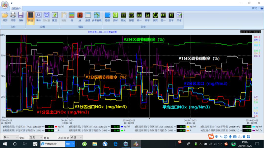
Figure 13: Zoned Ammonia Injection Control of a Certain 300MW Unit
3. Application Summary
By applying iFOC intelligent denitrification technology, both the adjustment quality and stability of denitrification control have improved, significantly reducing environmental assessments caused by exceeding SCR system outlet concentration limits, improving the operational conditions of the air preheater, and saving approximately 100,000 to 200,000 in ammonia usage annually.
5. iFOC Intelligent Soot Blowing Technology
1. Technical Route
The main purpose of intelligent soot blowing is to improve the thermal conductivity efficiency of the heat transfer medium, reduce the thermal energy waste of steam, and minimize the erosion and thinning of heated metal surfaces, thereby enhancing the overall energy conversion efficiency of the unit system and improving economic benefits.
The iFOC intelligent soot blowing technology starts from the characteristics and mechanisms of ash deposition on heated surfaces, segmenting historical wall temperature curves according to step-decay conditions, and utilizing LSTM (Long Short-Term Memory) neural network methods to model the slagging process and trends at various wall temperature measurement points in the furnace, generating a monitoring model for slagging on the water-cooled walls of the furnace. Simultaneously, by establishing dynamic fouling models corresponding to screen over, high over, high reheating, low reheating, low over, economizer heated surfaces, and air preheaters, a boiler intelligent soot blowing system based on the DCS system has been developed, achieving “on-demand and appropriate” intelligent soot blowing, automatic drainage, and automatic start-stop during daily boiler operations, avoiding “under-blowing” and “over-blowing,” ensuring the safety of the boiler’s heated surfaces, effectively reducing the frequency of soot blower operations and steam consumption, improving heat transfer efficiency, and lowering flue gas temperature, thus achieving energy conservation and consumption reduction for the unit.
The program flow chart for intelligent soot blowing is shown in Figure 14. The soot blowing optimization control module intelligently controls each unit based on soot blowing demand, operational time after soot blowing, drainage temperature, and stop conditions.
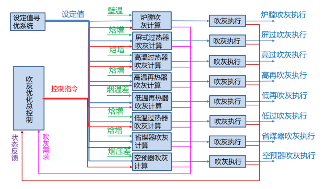
Figure 14: iFOC Intelligent Soot Blowing Program Flow Chart
2. Application Cases
A certain 330MW subcritical unit (Figure 15) adopted iFOC time-based linear intelligent soot blowing technology, and after 168 hours of unit operation, the average soot blowing frequency (after load rate correction) decreased from approximately 140.83 times to about 101.80 times, a reduction of about 27.71%; after the intelligent soot blowing was put into operation, the steam consumption for soot blowing was reduced by approximately 1014.7 tons/year; the flue gas temperature of the boiler decreased by about 2.24℃, corresponding to a 0.11% increase in boiler efficiency, and a reduction of 0.391g/kW·h in standard coal consumption, resulting in a cumulative direct economic benefit of approximately 1.036 million annually.
Figure 15: Application of Intelligent Soot Blowing in a Certain 330MW Unit
3. Application Summary
The iFOC intelligent soot blowing technology based on LSTM neural network modeling enables “on-demand and appropriate” intelligent soot blowing, automatic drainage, and automatic start-stop during boiler operation, with significant direct economic effects. Its indirect economic benefits can also be reflected in: ① Avoiding accidents caused by slagging and falling slag on the water-cooled walls; ② Reducing the frequency of soot blower operations, extending the lifespan of heated surfaces, and decreasing the probability of pipe bursts; ③ Reducing the operational burden on personnel and lowering daily maintenance costs, etc.
6. iFOC Soft Measurement
Soft measurement technology is part of the intelligent information processing technology within iFOC intelligent control technology. In addition to employing advanced control algorithms and systems, utilizing soft measurement technology can effectively improve and enhance the performance of control devices, serving as one of the effective means to improve the adjustment quality of control systems. A brief introduction is as follows:
1. Online Measurement and Compensation for Dead Zones and Stickiness of Actuators
Whether electric or pneumatic actuators, their stickiness and dead zones exist to varying degrees. The entire stickiness phenomenon of the actuator device is not limited to the actuator itself but also includes the connection part to the valve (damper), where the dead zone and stickiness often exceed that of the actuator part. The dead zone and stickiness of the actuator device are nonlinear and time-varying, requiring real-time compensation based on online detection of dead zone and stickiness amounts to adapt to changes in load and valve (damper) wear. Therefore, the compensation scheme should not only introduce the position feedback signal of the actuator but also the corresponding medium flow signal of the valve (damper) opening to achieve online measurement and adaptive compensation of the stickiness amount of the actuator device.
● Dead Zone and Stickiness Compensation for Actuators
The control system for dead zone and stickiness compensation of actuator devices is shown in Figure 16.
In Figure 16: is the controller;
 is the dead zone and stickiness link of the actuator;
 is the actuator;
 is the controlled object.
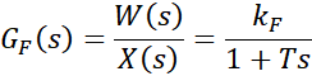
Since the valve-flow object is typically a first-order inertial link.
Where: kF is the gain of the valve-flow object; T is the inertial time of the valve-flow object.
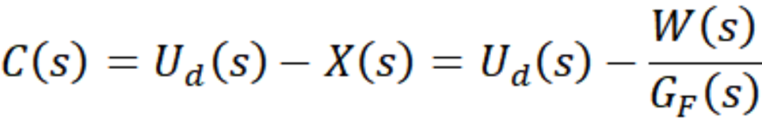
Due to the influence of the inertial time T of the valve-flow object on the measurement of actuator stickiness and the unmeasurability of signals, in the dead zone and stickiness compensation calculations, it is necessary to deduce the inverse operation of  to obtain the calculated value of the stickiness compensation.
 is the open-loop transfer function:
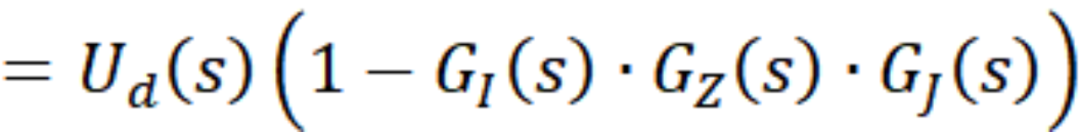 As the actuator device’s stickiness compensation signal, is no longer a set constant but a real-time detected compensation amount related to the stickiness of the actuator and connection device.
● Handling of Actuator Gaps
Since is based on the open-loop transfer function, to avoid disturbances from calculation errors in practical applications, detection, calculation, memory, and assignment to should be performed whenever the control signal change rate approaches zero. During this monotonous change period of the control signal, the compensation based on the memorized stickiness amount is implemented until the next cycle of detection, calculation, memory, and assignment.
● Constraints for Dead Zone and Stickiness Compensation of Actuators
To more effectively address potential oscillations or steady-state errors caused by oscillations and to achieve precise control, a two-dimensional discriminative signal for the threshold of the controller output signal and the time interval of the signal’s reverse action is introduced, as shown in Figure 17.
The principle of actuator stickiness compensation constraints is:
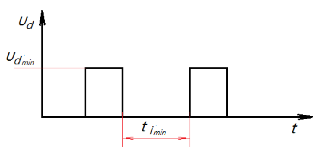
Figure 17: Discriminative Signals for Amplitude and Time Interval
① If the change amplitude of the control command is less than the threshold and the time of reverse action is less than the set time interval, the stickiness compensation signal is constrained; ② If the change amplitude of the control command is greater than the threshold or the change amplitude is less than the threshold but the time of reverse action is greater than the set time interval, the stickiness compensation signal is not constrained.
The introduction of the time interval aims to reduce steady-state errors and shorten the adjustment time. When the change amplitude of the control command is less than the threshold and the time of reverse action exceeds the set time interval, the stickiness compensation effect of the actuator device exists. Through this improvement, potential small oscillations in the control loop are avoided, and steady-state errors are effectively reduced, enhancing control precision.
● Simulation Verification Effects
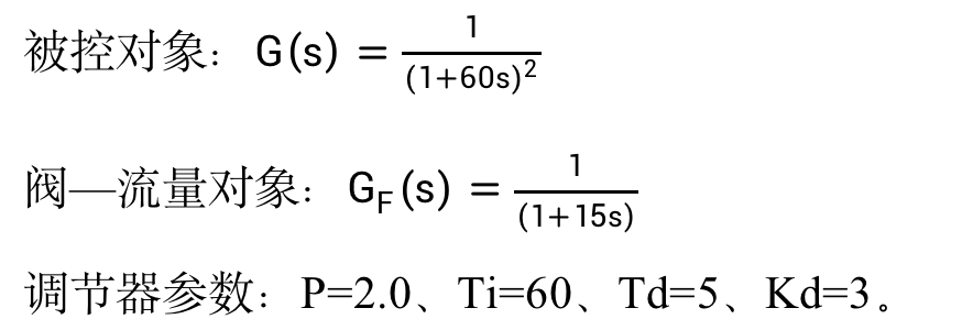
Figure 18 shows the simulation test of variable dead zones, demonstrating the process of adaptive stickiness compensation under random control signals, where the actuator dead zone changes from ±1% to ±2%.
Figure 19 shows the control performance comparison test curves with and without stickiness compensation loops. Test conditions: identical object characteristics, identical control parameters, actuator dead zone set to 2%, connection part dead zone set to 4%.
Before the setpoint step disturbance, the continuous reverse output suppression switch is in the OFF state, and the actuator output with the compensation loop exhibits small oscillations. When the continuous reverse output suppression switch is in the ON state, the small oscillations of the actuator output are suppressed.
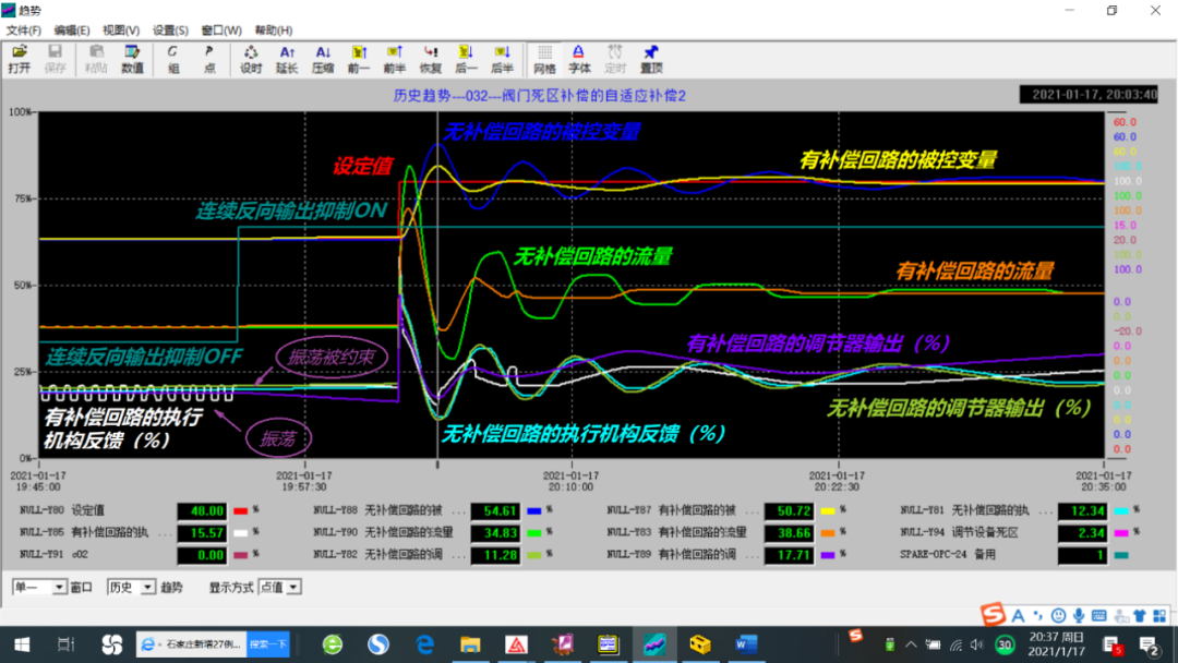
Figure 19: Control Performance Comparison Test with and without Stickiness Compensation Loops
Under experimental conditions, the control system with a stickiness compensation loop exhibited approximately 50% less overshoot compared to the system without a stickiness compensation loop, significantly improving control quality.
2. Soft Measurement of Desuperheater Outlet Temperature
● Soft Measurement Principle
Based on the principle of thermal balance, the calculation formula for the enthalpy of steam at the desuperheater outlet is:
Where: enthalpy of desuperheated steam (kJ/kg); flow splitting coefficient of steam; enthalpy of inlet steam at the desuperheater (kJ/kg); steam flow (t/h); total amount of desuperheating water (t/h); enthalpy of overheating cooling water (kJ/kg); flow of desuperheating water (t/h).
Thus, the outlet steam temperature of the desuperheater can be obtained as:
Where: outlet steam temperature of the desuperheater (℃); outlet steam pressure of the desuperheater (MPa).
Application Example 1:
A certain 330MW unit’s steam temperature system could not operate normally for a long time. After inspection, it was found that the measured value of the A side second-stage desuperheater outlet temperature was abnormal (the measured value of the desuperheating water amount changed, but the outlet temperature remained almost unchanged). After employing soft measurement technology for the desuperheater outlet temperature, the measurement issue was resolved, ensuring the normal operation of the steam temperature control system.
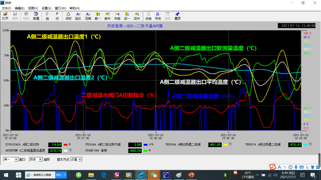
Figure 20 shows a comparison of the measured value of the A side second-stage desuperheater outlet temperature and the soft measurement results.
Figure 20: Comparison of Measured Value and Soft Measurement Results of A Side Second-stage Desuperheater Outlet Temperature
Application Example 2:
A certain 600MW unit’s reheating desuperheater experienced nozzle wear, causing the reheating desuperheating water to directly spray onto the temperature measurement element when the reheating desuperheating water valve was opened wide, resulting in frequent saturation temperature states as shown in Figure 21. After employing soft measurement technology for the reheating desuperheater outlet temperature, the measurement issue was resolved, ensuring the normal operation of reheating steam temperature. Figure 22 shows a comparison of the reheating desuperheater outlet steam temperature and soft measurement results.
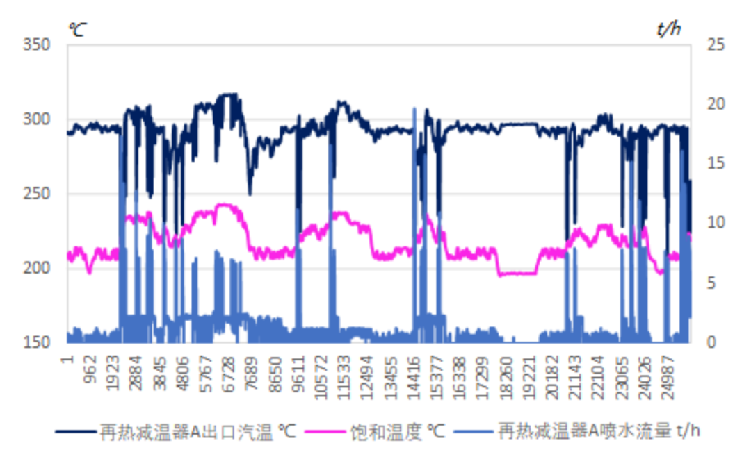
Figure 21: Reheating Desuperheater Outlet Frequently Exhibiting Saturation Temperature State
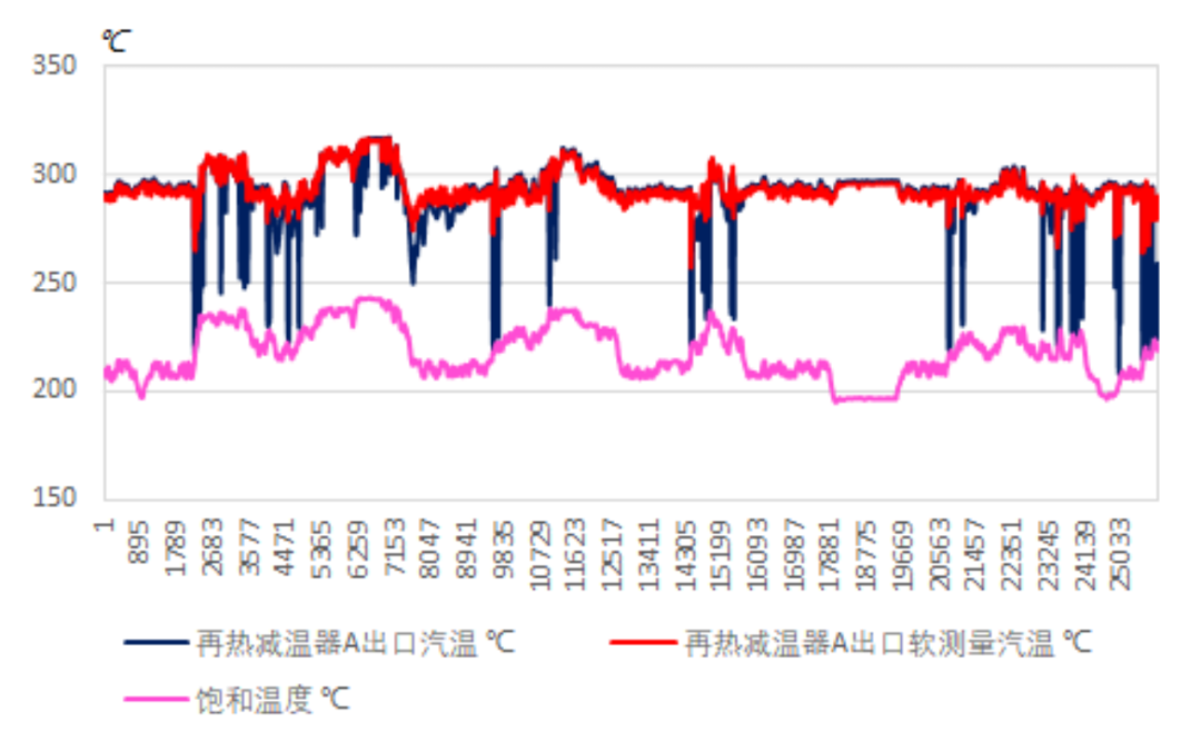
Figure 22: Comparison of Reheating Desuperheater Outlet Steam Temperature and Soft Measurement Results
3. Online Soft Measurement of Raw Coal Heating Value
Monitoring the elemental content and heating value of coal fed into the boiler has always been a challenge. Currently, the main method used domestically is dual-energy ray transmission measurement, which requires expensive hardware equipment, making its application in domestic thermal power units relatively rare. Most power plants do not have the conditions for online real-time measurement of coal quality, and the detection methods for incoming coal quality are mostly still at the level of manual sampling, preparation, and testing, leading to significant delays and sampling errors.
● Theoretical Basis
Where: low heating value of raw coal (kJ/kg); effective heat absorption of the boiler (kJ); flue gas losses (kJ); coal amount (kg/h); mechanical incomplete combustion (%), chemical incomplete combustion (%), boiler heat loss (%), and physical heat loss of ash and slag (%).
● Algorithm Module
The raw coal heating value calculation module is shown in Figure 23.
Figure 23: Raw Coal Heating Value Calculation Module
4. Online Soft Measurement of Raw Coal Moisture Content
● Theoretical Basis
By measuring parameters such as the output of the coal mill, the inlet air volume of the coal mill, and the temperature of the drying agent entering and exiting the coal mill, the monitoring of the moisture content of the incoming coal can be indirectly achieved.
Ultimately, a quadratic equation is obtained:

5. Application of Raw Coal Soft Measurement
The calculation of total moisture content and low heating value of raw coal is shown in Figure 24. It should be noted that these calculations are related to the efficiency of the boiler, implying that they are based on the performance calculations of the unit.
Figure 24: Calculation Framework for Total Moisture Content and Low Heating Value of Raw Coal
The recorded curves of total moisture content, low heating value, and boiler reverse balance efficiency are shown in Figure 25.
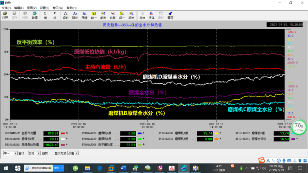
Figure 25: Recorded Curves of Total Moisture Content, Low Heating Value, and Boiler Reverse Balance Efficiency
6. Application Summary
The application of soft measurement technology effectively improves and enhances the performance of control systems, serving as one of the main means to achieve intelligent control.
The stickiness characteristics of actuators are an important component in the study of control loop performance. An online detection method for the stickiness characteristics of actuator devices has been proposed, along with a real-time calculation of compensation amounts; a two-dimensional constraint processing method for thresholds and time intervals has been introduced, which can effectively improve the performance of closed-loop control systems. While meeting grid load demands, it enhances the control quality of various control systems in the unit, achieving precise control objectives.
The soft measurement technology for desuperheater outlet temperature resolves measurement inaccuracies in desuperheater outlet temperature measurement, creating conditions for the normal operation of the steam temperature control system.
Additionally, the online soft measurement technology for raw coal heating value and total moisture content, based on the DCS-based unit performance calculation system, also creates favorable conditions for subsequent intelligent optimization of the unit.
7. Introduction to the Solution Provider
Shanghai Xinhua Control Technology Group Co., Ltd., part of the automation business segment of the Chint Group, is a high-tech enterprise dedicated to automation, digitalization, and intelligence.
Its predecessor, the China Electric Hydraulic Control Technology Development Center, was established in 1985, focusing on the research and production of control systems for thermal power generation equipment. In the early 1990s, Xinhua developed and successfully commissioned China’s first domestic data acquisition system for thermal power plants (referred to as “DAS”), a digital hydraulic regulation system for large steam turbines (referred to as “DEH”), and a distributed digital control system for large thermal power units (referred to as “DCS”), becoming a strong R&D, production, and engineering base for DEH and DCS in China’s thermal power industry, aiming to become a leader in China’s industrial automation sector.
8. Introduction to the Author Team
Zhao Weijie (1956-), male, senior engineer, Deputy Chief Engineer of Shanghai Xinhua Control Technology Group Co., Ltd., engaged in research and application of industrial automation and control algorithms.
Yan Xinbo (1982-), male, Manager of the Smart Power Plant Department of Shanghai Xinhua Control Technology Group Co., Ltd., engaged in business cooperation and application in smart power plants.
Chen Jing (1982-), male, PhD, Product Manager of Smart Power Plant at Shanghai Xinhua Control Technology Group Co., Ltd., engaged in management and R&D of intelligent optimization product lines.
Yu Wensheng (1972-), male, senior engineer, Chief Engineer of Intelligent Optimization at Shanghai Xinhua Control Technology Group Co., Ltd., engaged in the promotion and application of intelligent optimization technology for thermal power units.

Initial Review: Zhu ShihongRe-review: Liu XiaoAudit: Wang Hongsheng