 MAKER: Shiura /Translated by: Qu Wujin
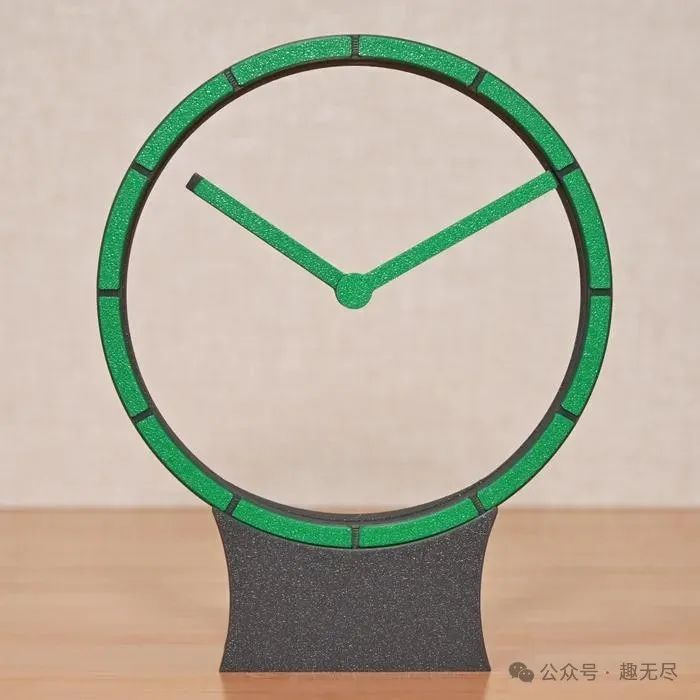
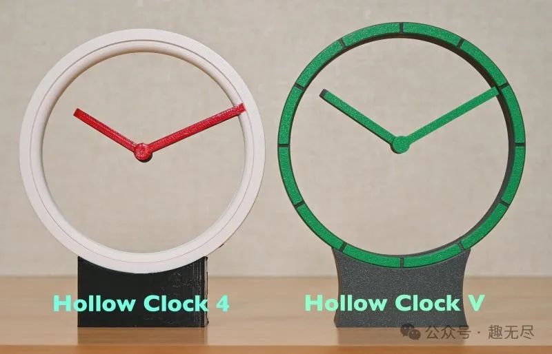
The fifth generation of the “Hollow Clock” is a comprehensive improvement and refinement based on previous versions.
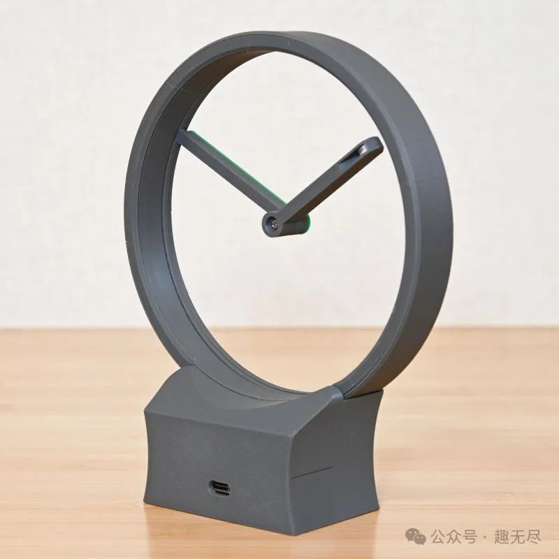
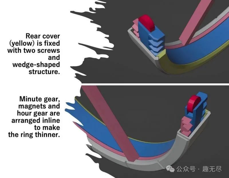
This clock features a thinner and cleaner ring design (only 7mm), complete with scale markings. Its appearance has almost no exposed screw heads (except for the center of the hands), making the design more exquisite. The USB-C power interface is cleverly placed on the back of the base, combining practicality and aesthetics.
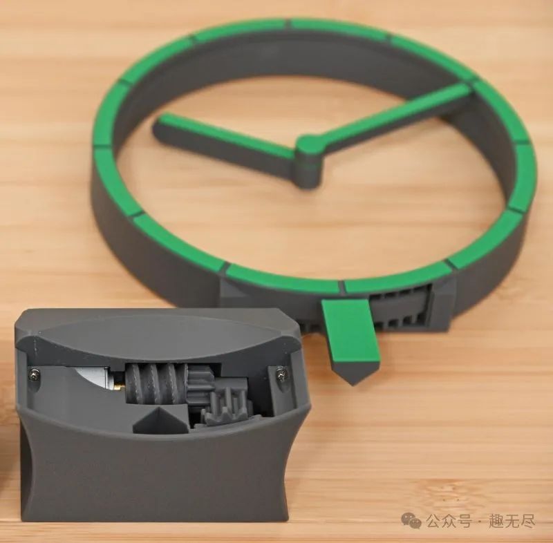
The new version introduces a ratchet mechanism that effectively prevents the clock from being inaccurate or skipping steps due to insufficient power from the stepper motor, greatly enhancing the clock’s reliability. At the same time, the clock’s accuracy has achieved a qualitative leap based on the crystal oscillator of the RP2040 microcontroller.
Continuing from the previous model, we have retained the convenient time adjustment method—simply pull out the display ring to adjust, then insert it back into the base. In this upgrade, the display ring’s fixation method is more secure, providing greater peace of mind.
In terms of overall design, we have made comprehensive innovations, fully utilizing the texture characteristics of the building board and layer lines. The front surface of the clock cleverly integrates the texture of the building board, showcasing a unique feel and aesthetic.
Material List
– Motor: 28BYJ-48 reduction stepper motor and driver board (about $3/set).
– Microcontroller: RP2040 development board, PicoBit, RP2040-Zero or compatible products.
– Magnets: Three 8x3mm neodymium magnets.
– Screws: 2mm flat head self-tapping screws.
– Wires, glue, lubricant.
Tools include screwdrivers, soldering tools, blades, scrapers or files, etc., for removing debris, smoothing surfaces, and chamfering.
All components do not require additional support structures. When giving different colors to the “rotor shell-front” scale ring, please change the material at a height of 0.6mm (the depth of the scale ring groove is 0.75mm). Similarly, you can also color the “hour hand” in this way.
The “minute hand-color part” is optional. Besides giving it different colors by changing the filament, you can also paste this part after printing is complete. Since the front surfaces of the “rotor shell-front”, “hour hand”, and “base-front” come into contact with the building board, they will show the texture of the building board. Therefore, to maintain consistency in texture, it is recommended to print the “minute hand-color part” separately.
Download the 3D printing files from the file library: https://make.quwj.com/project/525
Hardware Assembly
– Remove ULN2003 IC: To leave more soldering space, please remove the IC from the ULN2003 driver board in advance.
– Trim the pins: It is recommended to trim (cut) the four pins of the ULN2003 driver board pin header for easier soldering.
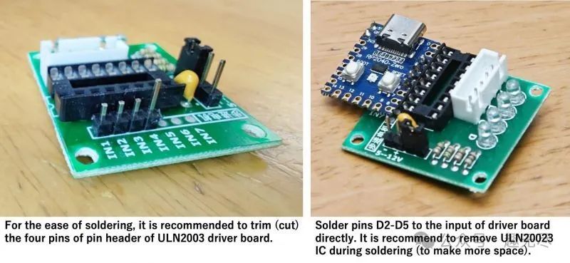
– Solder the pins: Directly solder the D2-D5 pins to the input side of the driver board. Please be careful not to touch the tiny chip on the microcontroller while soldering.
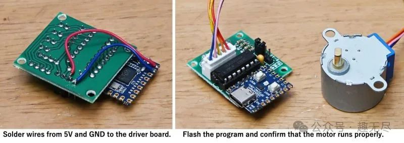
– Connect the power and ground wires: Use wires to connect 5V and GND to the driver board.
Software Setup
Test code: Use Arduino IDE to upload the test-code.ino file to your microcontroller and confirm that the motor can rotate normally. Clock code upload: After confirming that the test is correct, upload the clock code. Using precompiled binary files: If you do not want to install Arduino IDE, we provide precompiled binary files (.uf2 format). First, hold down the BOOTSEL button and connect the microcontroller to USB. Then, drag and drop the .uf2 file onto the mounted drive.
You can download the code and library files from the file library: https://make.quwj.com/project/525
Please watch the assembly guide video provided above.
Assembling the Display Ring
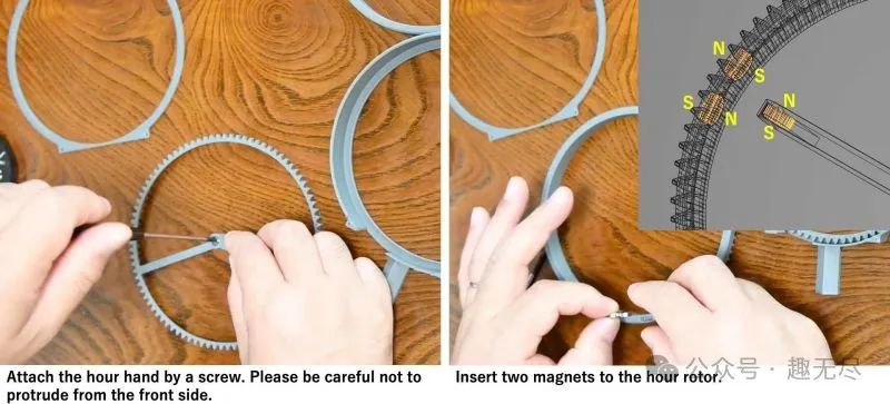
Install the hour hand: Fix the hour hand to the display ring with screws, ensuring that the hour hand does not protrude from the front. Install the magnets: Place two magnets in the hour hand rotor.
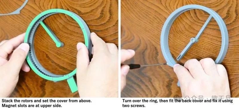
Stack the rotors and install the cover plate: Stack the rotors and place the cover plate on top. The magnet slot is located on top. Flip and secure the back cover: Flip the display ring, install the back cover, and secure it with two screws.
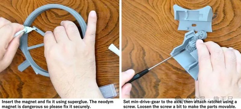
Secure the hour hand magnet: Insert the magnet into the hour hand and secure it with strong glue. Please note that neodymium magnets are dangerous to children, so ensure they are securely fixed.
Base Assembly
Install the minute hand drive gear: Place the minute hand drive gear on the shaft, then use screws to install the ratchet. Slightly loosen the screws to ensure the parts can move. Install the motor and driver board: Insert the motor shaft into the worm gear, then install the entire assembly into the casing. Insert the driver board into the reserved slot.
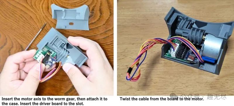
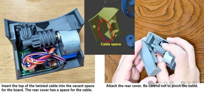
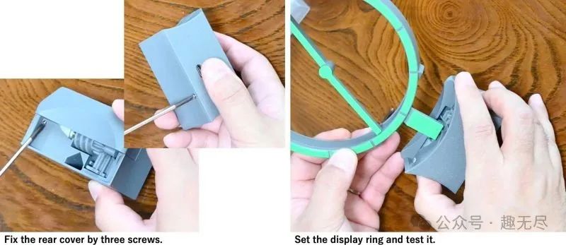
Organize the cables: Twist the cables connecting the board and motor, and insert the cable tops into the free space at the back of the board. The back cover has a cable passage. Install and secure the back cover: When installing the back cover, be careful not to pinch the cables. Secure the back cover with three screws.
Install the display ring and test: Place the display ring on the base and conduct a test.
For detailed installation steps, please watch the assembly guide video provided above.
Troubleshooting
– Assemble all parts according to the video guide.
– Ensure that the motor, gears, and magnets are correctly installed and secured.
– Use Arduino IDE to upload the code to the microcontroller and ensure the motor operates normally.
– If the clock runs very smoothly, you can remove the ratchet hook to silence the clock. In this case, set a smaller number for the “SAFETY_MOTION” value (not recommended to set to 0).
– Using lubricant helps reduce friction, but do not use too much to prevent parts from sticking.
The links in the text can be clicked to view “Read Original” at the end of the article