
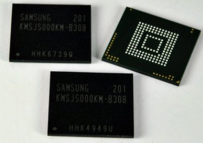
Understanding eMMC Chips
eMMC chips are a type of embedded multimedia card (Embedded MultiMediaCard) that integrates flash memory and a controller, primarily used in mobile devices such as smartphones and tablets for storing operating systems, applications, data, and images. Whether an eMMC chip supports a specific function depends on the specifications and design of the controller and flash memory chip.
Main Features of eMMC Chips
High Integration
eMMC chips integrate a controller to manage the flash memory, simplifying the product design process and accelerating product launch.
Unified Interface
eMMC uses the MMC standard interface, allowing compatibility with various storage devices, including NAND storage devices and MMC devices.
Large Capacity
Common capacities for eMMC range from 2GB to 256GB, meeting users’ demand for large storage.
High-Speed Transmission
eMMC chips support high data transfer rates, which can reach up to 400MB/s or higher, depending on their version and specifications.
Strong Compatibility
eMMC chips are compatible with various mobile devices and computer systems, including Windows, Mac, and Android.
Pin Configuration of eMMC Chips
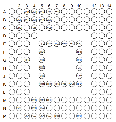
eMMC chips are a type of solid-state flash memory card, and their pin definitions differ slightly from those of standard SIM or SD cards. Therefore, when using them, appropriate modifications must be made based on specific hardware devices and chip specifications. As eMMC chips are widely used in mobile devices, understanding their pin definitions and working principles also aids in better data communication and operation. Below is a brief introduction to the pins using KLM8G1GETF as an example:
VCC/VCCQ
VCC is the power supply pin for the flash memory, typically 3.3V; VCCQ is the power supply pin for the memory controller.
CLK
Clock input pin issued by the main processor to the eMMC chip.
DATA Strobe
Data strobe pin that provides the main processor with selection signals from eMMC. In HS400 mode, reading data and CRC responses are synchronized with the data strobe.
DATA0-DATA7
Data bus for bidirectional data transmission mode “pull-up”. eMMC defaults to 1-bit mode but can also operate in 4-bit or 8-bit modes.
RSTN
Reset pin, active low. Therefore, a resistor is generally pulled up to keep the default high level without resetting.
CMD
Bidirectional signal used for device initialization and command transmission. Commands operate in two modes: open-drain for initialization and push-pull for fast command transmission.
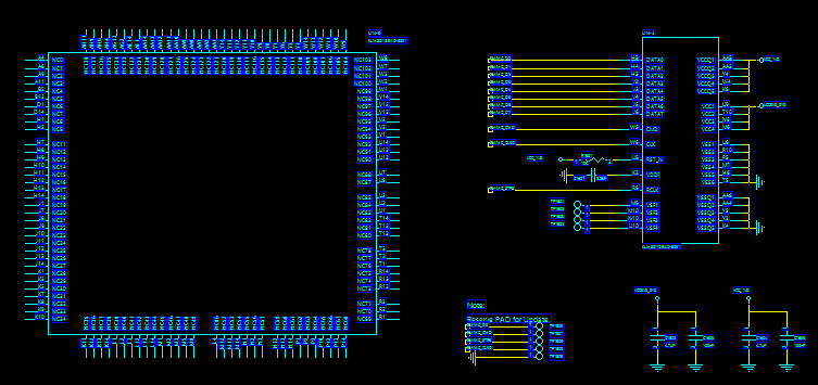
PCB Design for eMMC Chips
The PCB design for eMMC chips needs to consider multiple aspects, including power and interface, layout and routing, protection, heat dissipation, testing, and debugging, to ensure the performance and reliability of the eMMC and meet device requirements.
Power and Ground Lines
Ensure a stable power and ground supply for the eMMC chip. The power lines should be wide enough to handle the chip’s power consumption needs and should minimize the length and impedance of the power lines.
Signal Line Length Matching
The signal line lengths for eMMC chips should be matched as closely as possible to reduce signal transmission delay and distortion. Differential pairs can be used to improve signal immunity.
Signal Line Routing
Avoid crossing signal lines with high power or high-frequency lines to minimize interference. Ground and power layers can be used to isolate signal lines.
Capacitance and Inductance
Add appropriate capacitance and inductance to the power and ground lines of the eMMC chip to provide a stable power and ground supply. The selection of capacitance and inductance should meet the recommendations of the chip manufacturer.
PCB Layout
Place the eMMC chip away from other high-power or high-frequency components to reduce interference, while minimizing the length of the signal lines to improve signal stability.
Pin Spacing and Routing Methods
Due to the small pin spacing of eMMC devices, when the internal pins cannot be routed, the following methods can be employed:
① When conventional routing cannot be achieved, a tight routing method can be used, where traces are routed with the minimum width between pads;
② If routing cannot be done with the minimum width, the pads can be modified to an elliptical shape to meet the minimum width routing spacing;
③ If routing is still not possible, blind vias can be created on the pads to route on another layer.
Design for Manufacturability of eMMC Chips
Line Width and Spacing
The minimum line width and spacing is generally 3 mils. The design of the minimum line width and spacing must meet process requirements; exceeding the manufacturing capability may result in the PCB being unproducible or the produced boards having a very low yield, leading to high costs.
Pad Size
The size of the pads affects the soldering quality. Pads that are too small may not be solderable at all. The minimum pad size is generally 0.2mm; pads smaller than 0.2mm may lead to etching failures, causing the board to be scrapped.
Via-in-Pad
Via-in-pad refers to the holes on the SMT solder pads. Via-in-pads generally require resin-filled vias, which are then plated with copper to meet soldering requirements. If there are no resin-filled vias, the reduced solder area may lead to poor soldering.

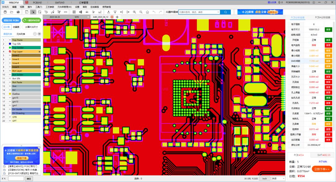
Here we recommend a simple and easy-to-use tool specially developed for PCB and PCBA inspection: Huaqiu DFM Software. This manufacturability check software can check the minimum line width, line spacing, pad size, solder mask bridge, etc., for the PCB manufacturability of eMMC chip packaging locations, and also helps to preemptively prevent manufacturability issues for eMMC chip packaging locations.
Download link for Huaqiu DFM Software (copy to your computer browser):
https://dfm.elecfans.com/uploads/software/promoter/hqdfm_DFMGZH.zip
Exclusive Benefits
Downloading from the link above also grants a 50 yuan discount on the first order for multilayer boards
Once a month, free prototyping for 4-layer boards
And receive multiple no-threshold “components + board fabrication + SMT” coupons
This statement is published to convey more information. If there are errors in source attribution or infringement of your legal rights, please contact the author with ownership proof, and we will promptly correct or delete it. Thank you.
Advertisement