EMMC Socket Usage:
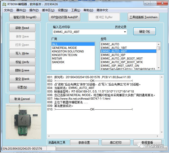
Enter “EMMC” under “Input Chip Marking” to see the following three options:
EMMC_AUTO: Speed 8BIT (default), automatically recognized when EMMC.
EMMC_AUTO_4BIT: 4BIT, recommended for most chips for stability.
EMMC_AUTO_1BIT: 1BIT, can be selected when the above two cannot read; slower speed but may recover data in the chip.
Additionally, the chip model suffix _1/4/8BIT@FBGA153/FBGA169, etc. (where 1/4/8BIT indicates different speeds; FBGA153 and FBGA169 indicate chip packaging types), are actually consistent with the above three options, just that the first three do not require distinguishing the chip model for reading and writing.
Technical Improvement Methods for CRC Errors when Reading/Writing SanDisk, Kingston, and Toshiba Some Models:
Note:
① Ensure the chip is functioning properly; some chips that can read but not write, or cannot read at all, are bad signs.
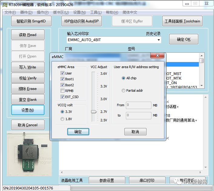
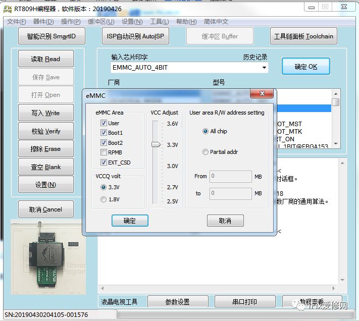
② When using the socket, VCCQ voltage should only be 3.3V; do not select 1.8V.
③ If the 8 resistors on the socket are not 100Ω[101], please replace them first; if that does not work, continue with the following operations.
Method 1: Under the EMMC option, click on the left “Settings” and adjust VCC Adjust to 2.7V before reading/writing;
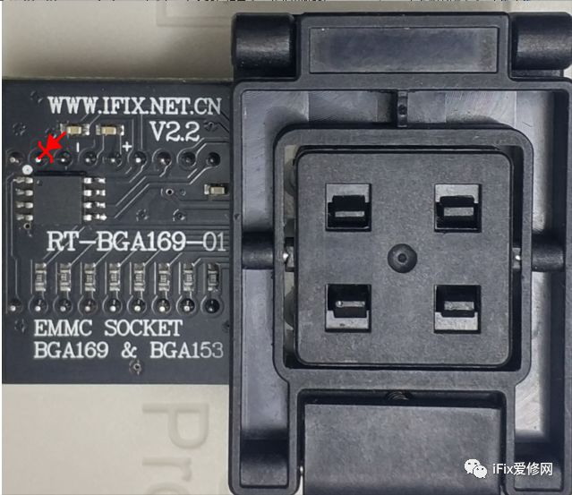
Method 2: Add a 5.1V voltage regulator to the second (CMD) and third pin (GND) on the left bottom of the EMMC socket; default VCC Adjust=3.3V can also read/write normally.
Below is a schematic for installing the voltage regulator for the new version V2.2:
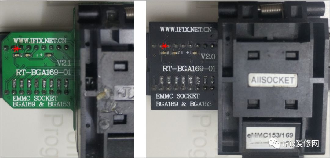
Below is a schematic for installing the voltage regulator for the original versions V2.1 and V2.0:
Choose one of the above methods; for serial numbers after 201903, RT809H has directly adjusted parameters on the motherboard and is not included in the impact.