
Overview of EMMC Protocol
Whether EMMC V4.5 or V5.1, the protocol can be quite extensive, making it difficult for newcomers to grasp the key points or analyze effectively. This article mainly summarizes some important and commonly used aspects of the EMMC protocol.
1. Basic Understanding of EMMC
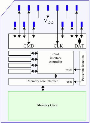
1.1 Physical Lines:
| Physical Interface | Interface Meaning |
|---|---|
| CLK | Clock line, each cycle of this signal controls the transmission of 1 bit on the command line, as well as 1 bit (1x) or 2 bits (2x) on all data lines. |
| CMD | Command line, this signal is a bidirectional command channel used for device initialization and command transmission. The CMD signal has two operating modes: open-drain mode for initialization and push-pull mode for fast command transmission. |
| DAT0-7 | These are bidirectional data channels. DAT signals operate in push-pull mode. In the default state, only DAT0 is in push-pull mode, while DAT1-7 are in pull-up (internal pull-up), and after entering 4-bit mode, DAT0-3 are in push-pull. |
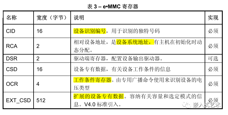
1.2 Understanding EMMC Related Registers
1.3 Other Features
-
Read/Write Mode: Single block read/write, multiple block read/write
-
Addressing Method: Byte addressing and sector addressing, byte addressing allows a maximum of 2GB, and for capacities exceeding 2GB, sector (512B) addressing is used.
-
Voltage Mode: Supports high voltage and dual voltage modes.
-
Supports enhanced partition mode, etc.
2. Bus Protocol
2.1 Basic Understanding
-
Command: A token to initiate an operation, the command is sent from the host to the device, transmitted serially on the CMD line. -
Response: A token sent from the device to the host as a reply to the previous command, transmitted serially on the CMD line. -
Data: Bidirectional transmission between the host and slave, the bus width can be 1-bit (default), 4-bit, or 8-bit.
2.2 Command Format
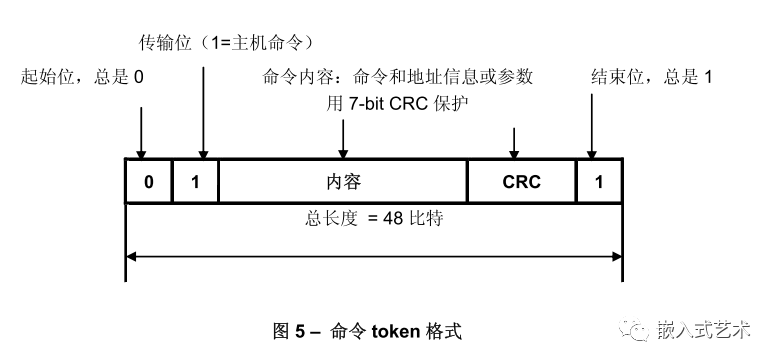
Each token consists of a start bit (‘0’) leading and a stop bit (‘1’) terminating. The total length is 48 bits. Each token is protected by CRC, allowing for detection of transmission errors, and can be repeated.
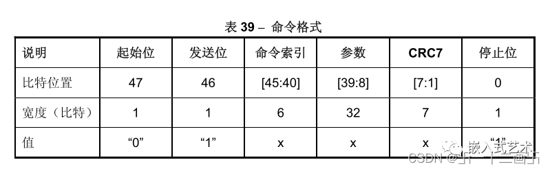
The command format can be divided into 4 types:
① No response broadcast command (bc)
② Response broadcast command (bcr)
③ Point-to-point addressing command (ac), no DAT data
④ Address data transfer command (adtc), with DAT data
Command Index: Refers to the command numbers such as CMDX 0, 1, 2, 3, etc.
Command Parameters: Some commands require parameters, such as address information.
2.3 Response Format
All responses are sent via the command line CMD, and the encoding length depends on the response type. Response Token types have 5 encoding schemes: R1, R2, R3, R4, R5. The Token length is 48 or 136 bits.
① R1 (Normal response type)
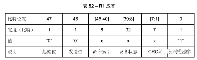
Encoding length 48bit, bits 45:40 represent the command index corresponding to the response, bit 8:39 indicates the status information of the device to be sent.
② R2 (CID CSD Register)
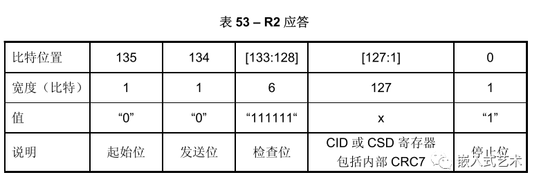
Encoding length 136bit, content of the CID register sent as a response to CMD2 and CMD10. The CSD register content is sent as a response to CMD9, and only bit 127:1 of CID and CSD registers are sent.
③ R3 (OCR Register)
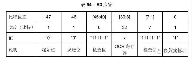
Encoding length 48bit, OCR register sent as a response to CMD1.
④ R4 (Fast I/O)
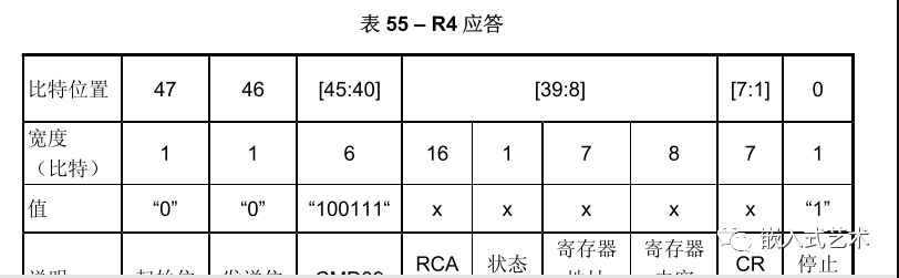
Encoding length 48bit, parameter field includes the RCA of the addressed device, the register address and content to be read/write.
⑤ R5 (Interrupt Request)
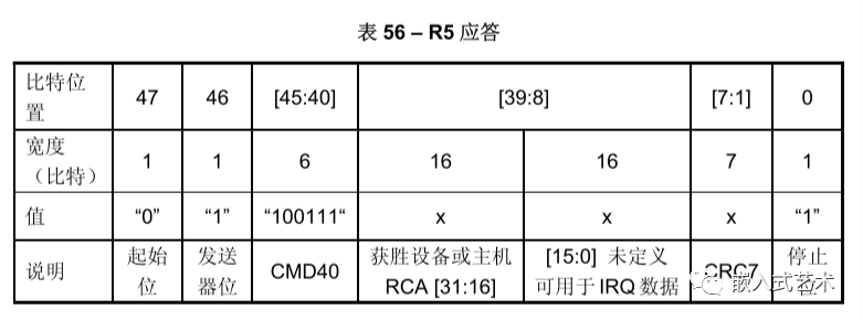
Encoding length 48bit, if the response is generated by the host, the parameter RCA should be 0.
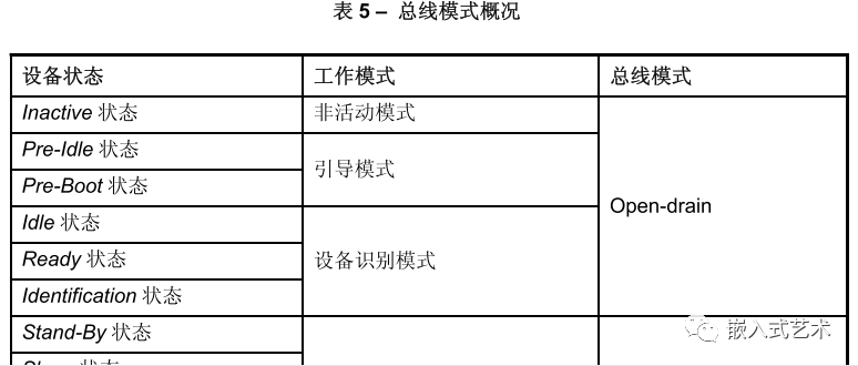
3. Working Modes
Communication between the host and the device is initiated by the host, which sends commands that elicit responses from the device.
The EMMC working modes are defined as 5 types:
-
Boot Mode: Puts the device in boot state. -
Device Identification Mode: After boot mode ends, the device accepts the SET_RCAcommand to identify the device. -
Data Transfer Mode: After assigning RCA, the device enters data transfer mode, ready for data communication. -
Interrupt Mode: Both host and device enter simultaneously, with no data transfer, allowing only messages from host or slave interrupt requests. -
Inactive Mode: If the device’s working voltage range and access mode are invalid, it enters inactive mode.

Each mode has its own characteristics. We mainly focus on understanding the device identification process and the data transfer process.
3.1 Device Identification Mode
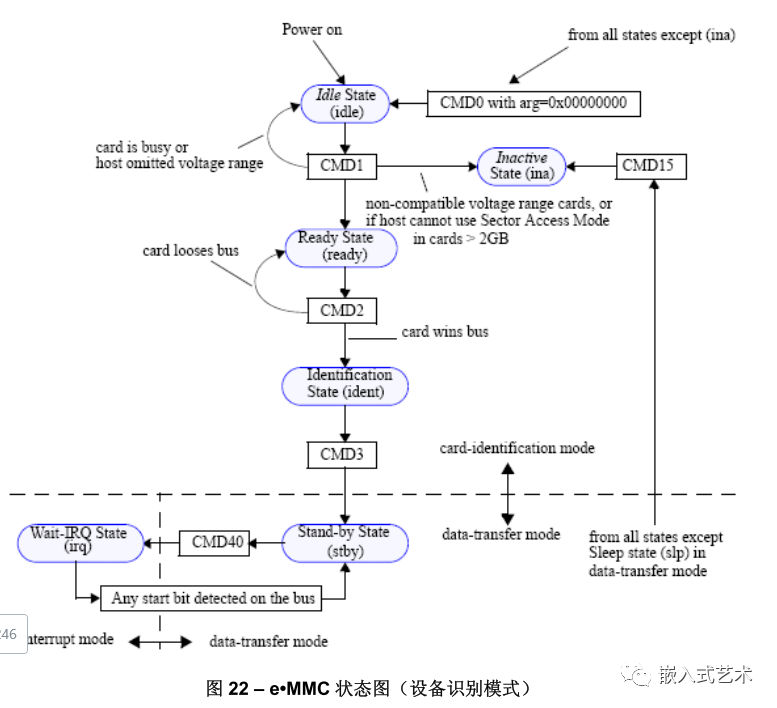
At first glance, the diagram may seem confusing. Without careful analysis of the protocol, understanding it solely from the diagram can be challenging.
Overall, in device identification mode, for the host to recognize the card, the main steps are as follows:
-
Reset Device
-
Verify Working Voltage and Access Mode
-
Identify Device and Assign Relative Device Address
RCA -
Put Device into Data Transfer Mode
3.1.1 Reset
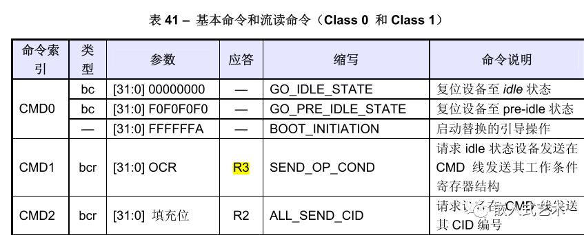
EMMC Controller sends CMD0 with parameters 0x00000000 to put the device into Idle state.
For backward compatibility, any parameters received that are not 0XFFFFFFFA or 0XF0F0F0F0 in any state except Inactive are treated as CMD0.
3.1.2 Verify Working Voltage and Access Mode
EMMC Controller sends CMD1 with parameters from the OCR Register, which includes 2bit of memory access mode.
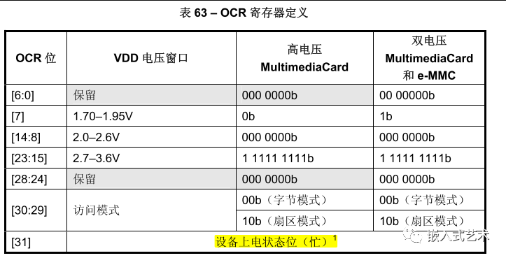
As shown, bit[30:29] indicates the access mode, and the purpose of sending this data via CMD1 is to synchronize the addressing type with the memory.
EMMC Device should also respond with a fixed pattern of 0x00FF8080 or 0x40FF8080 (if the device is busy), 0x80FF8080 (for capacity less than or equal to 2GB), or 0xC0FF8080 (for capacity greater than 2GB).
bit31 is used to indicate busy status; if it is 1, it indicates that the EMMC Device is still in the reset process, and the host should continuously send CMD1 to ensure that the busy bit is cleared.
3.1.3 Identify Device and Assign RCA
After checking with CMD1, devices that do not meet the requirements enter the Inactive state, while those that do meet the requirements enter the Ready state.
Then, the EMMC Controller sends CMD2 to request the qualifying device to send its unique device identifier CID. The CID number is unique to each card.
Devices that successfully send the CID enter the Identification state.
Next, the EMMC Controller sends CMD3 to assign a relative device address RCA to the device. Once the device receives the RCA, it transitions to Stand-by state, which is the data transfer state.
3.2 Data Transfer Process
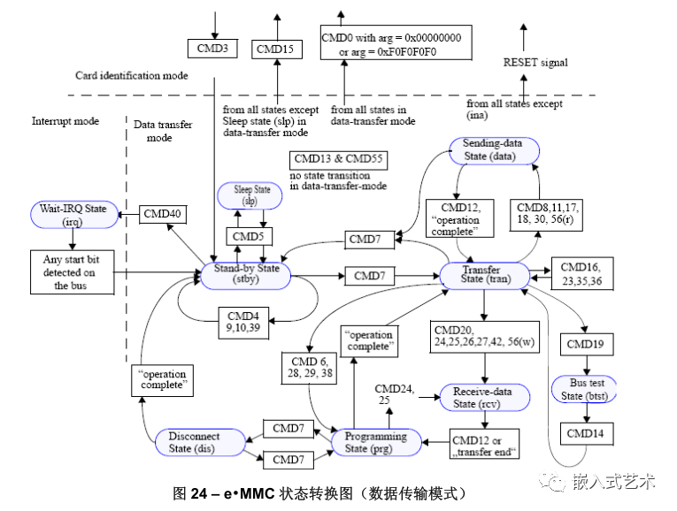
After assigning the RCA, when the slave device receives the RCA, it immediately enters stand-by state, and the CMD and DAT lines switch to push-pull mode.
3.2.1 Obtain CSD Register Information
CMD9: The host sends this command to obtain the device-specific register CSD data, such as block length, storage capacity, maximum clock rate, etc.
3.2.2 Obtain CID Register Information
CMD10: The host sends this command to obtain the device-specific register CID data, retrieving the device identification number.
3.2.3 Switch to Transfer State
CMD7: The host sends this command to select the device and switch it to the data sending state.
3.2.4 View EXT_CSD Extended Register
CMD8: The host sends this command, and the device sends its EXT_CSD register data as a data block of 512 bytes.
3.2.5 Modify EXT_CSD Extended Register Values
CMD6: The host sends this command to switch the working mode or modify the EXT_CSD register.
CMD6 command has significant parameter settings!
[31:26]: As stated in the manual, set directly to 0.
[25:24]: Access mode selection; what access modes are there?
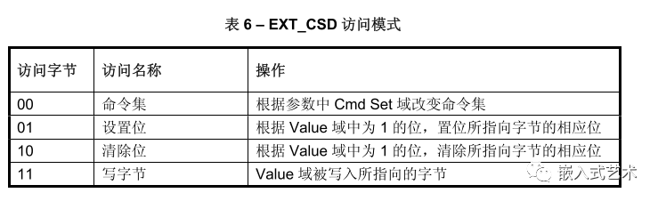
If the SWITCH command is used to change the command set (i.e., [25:24] = 00), the Index and Value fields are ignored (i.e., [23:16], [15:8] ignored), and the EXT_CSD will not be written.
If the SWITCH command is used to write to the EXT_CSD register, the Cmd Set field is ignored [2:0] ignored, and the command set remains unchanged.
[23:16]: Index, referring to the byte index of the EXT_CSD register to be modified.
[15:8]: The value to be written.
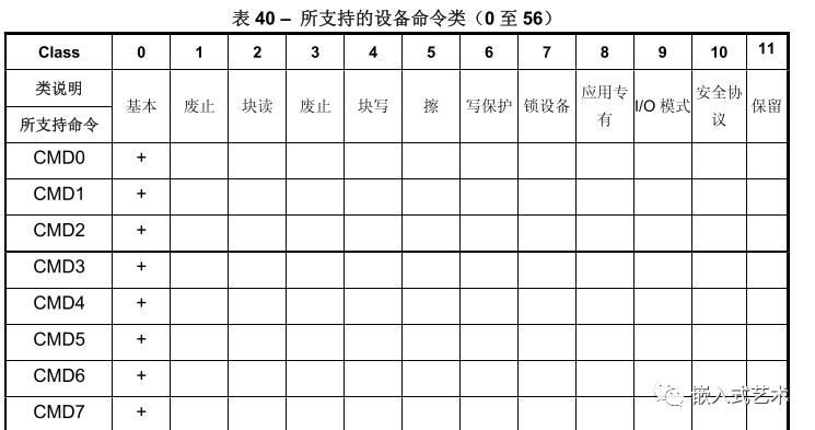
[2:0]: Command set selection, with various categories available in related manuals.
For example:
If we want to operate the bus width, how should we modify it?
Send CMD6 command with args=03B70200 to modify it.
03: Represents the access mode as write byte.
B7: Convert to decimal 183, corresponding to the byte of the EXT_CSD bus width mode.
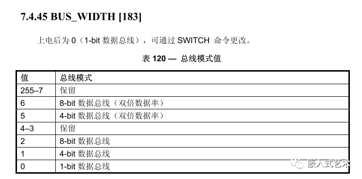
02: Set this byte’s value to 02, which means 8-bit data bus.

00: In write byte access mode, this bit is invalid.
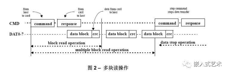
3.2.6 Read Data
-
Single Block Read
CMD17: Directly send the read command, with parameters for the data address information, reading only one block.
-
Multiple Block Read
CMD18: Directly send the read command, with parameters for the data address information, and continue reading.
CMD12: Stop command, to stop transmission.
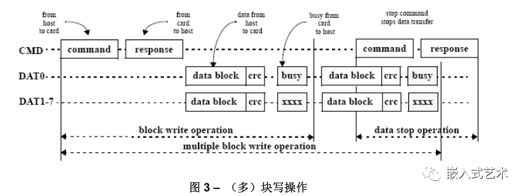
3.2.7 Write Data
Ensure the device is in sending state, i.e., the host sends
CMD7command.
-
Single Block Write
CMD24: Directly send the write command, with parameters for the data address information, writing only one block.
-
Multiple Block Write
There are two modes for multiple block writes:
① One mode is: Set the number of data blocks to be transmitted, and it will automatically stop after reaching the number.
CMD16: Set the number of blocks to be transmitted.
CMD25: Start sending data blocks specified by CMD16 until the specified number of data blocks is written.
② Another mode is: Continuously transmit data until a stop data command is received.
CMD25: Start sending data blocks, continuously waiting for data to be fully sent.
CMD12: Stop command, to stop transmission.

END