In the previous graduation project for the corporate network, some friends provided feedback that the project was too monotonous. After four years of university, this is indeed insufficient. Starting from this issue, we will discuss MPLS VPN! I hope everyone can understand it well enough to incorporate it into their graduation projects! If you need to learn more about the graduation project, you can click the text below to find out! The graduation project for network engineering is – Corporate Headquarters Network MSTP + VRRP, using OSPF to achieve three-layer intercommunication!
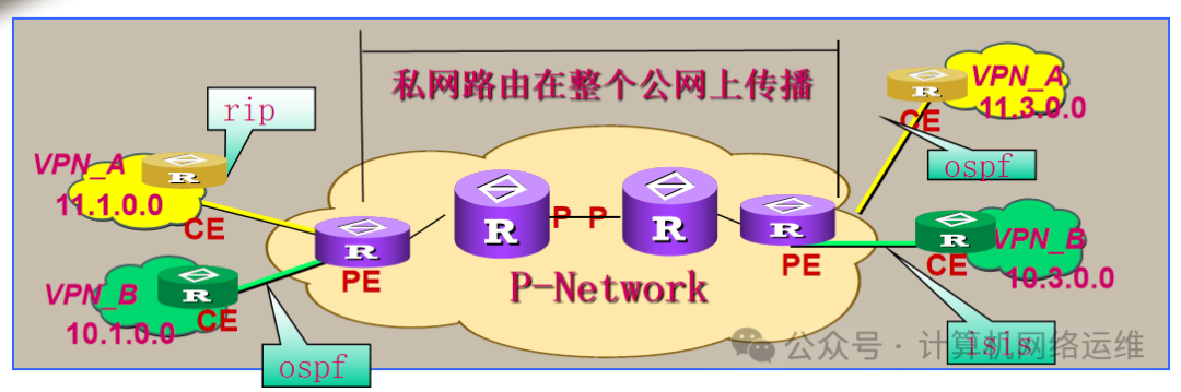
The MPLS network mainly consists of three parts: CE (Customer Edge Router) devices that connect directly to the service provider’s network; PE (Provider Edge Router) devices that connect directly to the customer’s CE and are responsible for VPN service access; and P (Provider Router) devices that are responsible for fast data forwarding. In the entire MPLS VPN, PE devices need to support the basic functions of MPLS, while CE devices do not need to support MPLS.
🎏MPLS VPN Technology
Alice (10.0.0.10) communicates with Bob (10.1.0.10). When receiving each other’s IP packets, the two IP addresses seen in the IP packets must be these two addresses and not others. In other words, what is sent is what is seen.
The list of operators’ MPLS VPN customers includes thousands of clients, all using the 10.0.0.0/8 network segment in their internal networks.
Since customers want to use the MPLS VPN network, they must have end-to-end communication, which means rejecting NAT involvement in the communication process.
However, a problem arises: we need to eliminate NAT technology while avoiding IP address conflicts among millions of customers. What technology can achieve both? This technology is MPLS VPN.
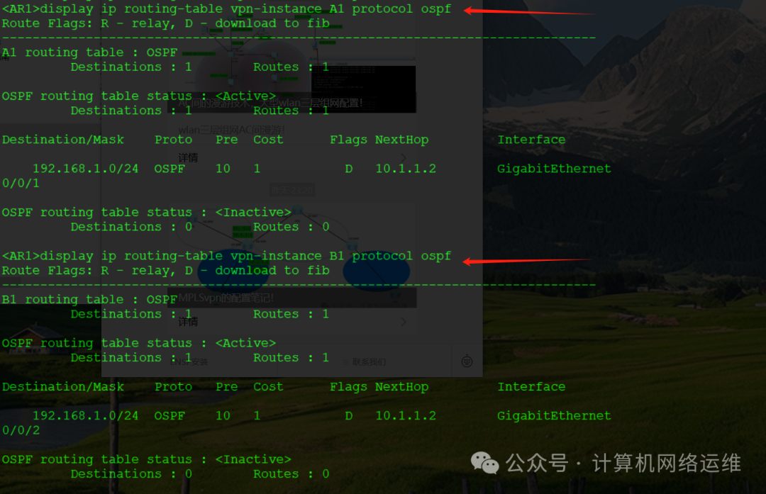
By sharing the PE link with CE, the VPN-instance resolves local routing conflicts!
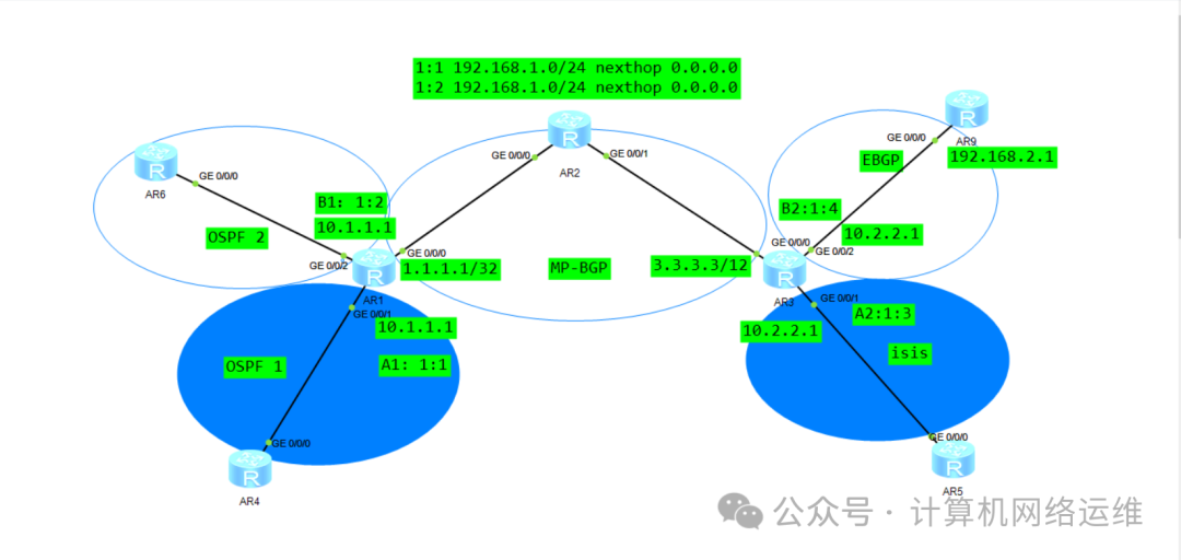
🎏Core Idea: Company A’s CE routers are AR4 and AR5, while Company B’s CE routers are AR6 and AR9
Company A’s AR4 with the 192.168.1.0 segment and AR5 with the 192.168.2.0 segment establish direct communication through MPLS-VPN. Company B’s AR6 with the 192.168.1.0 segment and AR9 with the 192.168.2.0 segment also establish direct communication through MPLS-VPN.
🎏Establishing Virtual Routing Table vpn-instance
[AR1]ip vpn-instance A1  Create a VPN instance named A1
[AR1-vpn-instance-A1]route-distinguisher 1:1   Create a virtual router named 1:1 (also called RD route distinguisher)
[AR1]ip vpn-instance B1  Create a VPN instance named B2
[AR1-vpn-instance-B1]route-distinguisher 1:2   Create a virtual router named 1:2
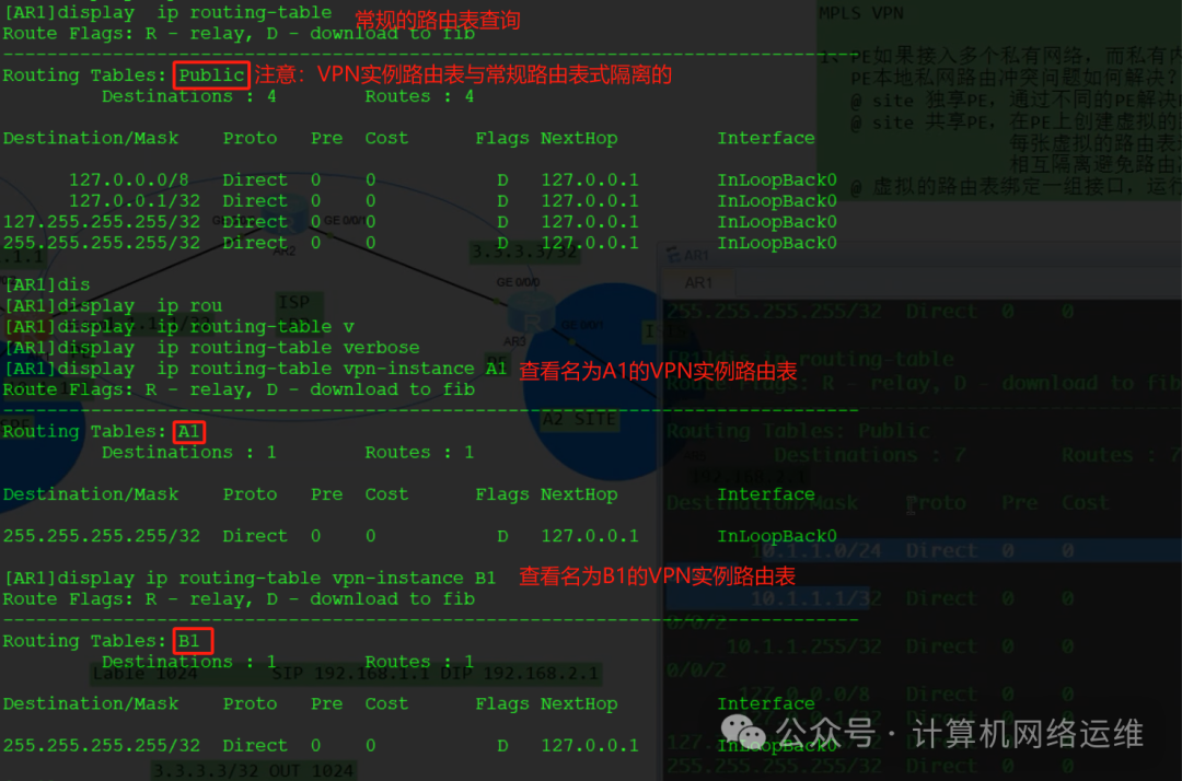
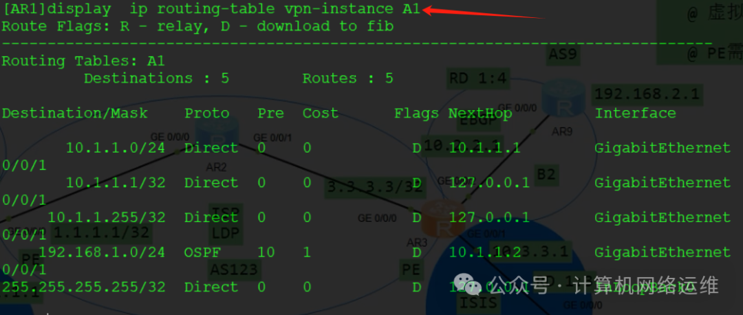
At this point, we have actually created two independent routing tables, and these two routing tables are isolated from the conventional routing table! This means that so far we have three routing tables! The names of these three routing tables are shown in the boxed area below, which are Public, A1, and B1.
🎏Binding Virtual Routing Table to a Set of Interfaces
[AR1-GigabitEthernet0/0/1]ip binding vpn-instance A1   Bind AR1's G0/0/1 to VPN instance A1
[AR1-GigabitEthernet0/0/2]ip binding vpn-instance B1   Bind AR1's G0/0/2 to VPN instance B2
This is equivalent to binding a physical interface to a virtual routing table! (Multiple interfaces can be bound to a virtual routing table)
🎏Physical Interface IP Address Configuration
[AR1-GigabitEthernet0/0/1]ip address 10.1.1.1 24  Configure IP address for G0/0/1 interface
[AR1-GigabitEthernet0/0/2]ip address 10.1.1.1 24  Configure IP address for G0/0/2 interface
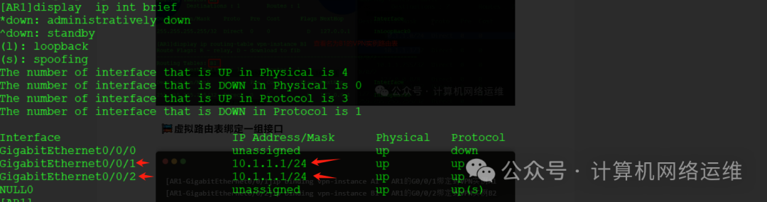
From the above image, we can see that both ports of AR1 are configured with the same IP address: 10.1.1.1, and there is no error. The reason is simple: it is equivalent to having a computer with two virtual machines, both running WPS, while the physical machine also runs WPS. A single computer can accommodate three WPS installations because two of them are installed on virtual machines, and since G0/0/1 and G0/0/2 are bound to different virtual routing tables, configuring the same IP will not have any impact! This is because VPN instance A1 and VPN instance B1 are completely isolated from each other, and the same applies to the conventional routing table! Through virtualization technology, we achieve shared PE, local routing isolation, and avoid IP conflicts in private networks on the same PE!
🎏Network Configuration of CE Router AR6 and AR1 Ports
Here, we refer to the operator’s router as PE, and the device connecting the operator’s router as CE!
[AR6-LoopBack0]ip address 192.168.1.1 24   Set the loopback IP address on AR6 to 192.168.1.1 24
[AR6-LoopBack0]ospf network-type broadcast  Set OSPF type to broadcast (if not set, the other party will receive a route with a 32-bit mask)
[AR6-GigabitEthernet0/0/0]ip address 10.1.1.2 24  Set IP address for the port connecting AR6 to PE
[AR6]ospf 1 router-id 6.6.6.6   Enter OSPF process 1 and set router ID to 6.6.6.6
[AR6-ospf-1-area-0.0.0.0]network 192.168.1.1 0.0.0.0
[AR6-ospf-1-area-0.0.0.0]network 10.1.1.2 0.0.0.0
🎏Network Configuration of CE Router AR4 and AR1 Ports
[AR4-LoopBack0]ip address 192.168.1.1 24   Configure the loopback IP address on AR4 to: 192.168.1.1 24
[AR4-LoopBack0]ospf network-type broadcast
[AR4-GigabitEthernet0/0/0]ip address 10.1.1.2 24
[AR4]ospf 1 router-id 4.4.4.4
[AR4-ospf-1-area-0.0.0.0]network 192.168.1.1 0.0.0.0
[AR4-ospf-1-area-0.0.0.0]network 10.1.1.2 0.0.0.0
🎏Network Configuration of PE Router AR1 Ports
[AR1]ospf 1 vpn-instance A1   On AR1, use OSPF process 1, and bind it to VPN instance A1
[AR1-ospf-1]area 0
[AR1-ospf-1-area-0.0.0.0]network 10.1.1.1 0.0.0.0  Declare 10.1.1.1 in OSPF process 1

[AR1]ospf 2 vpn-instance B1  OSPF process 2 bound to VPN instance B2
[AR1-ospf-2]area 0
[AR1-ospf-2-area-0.0.0.0]network 10.1.1.1 0.0.0.0
After configuring OSPF processes 1 and 2 for the two VPN instances, checking the OSPF neighbor relationship reveals that the neighbors of OSPF 1 and OSPF 2 are different! At this point, we have isolated the CE devices AR4 and AR6!
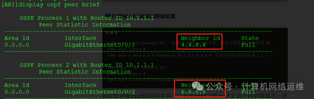
From the above image, we can see that a single PE device can connect to multiple CE devices at different sites, which is the essence of a VPN instance! Although AR4 and AR6 have the same IP address, they exist in parallel worlds and will not cause conflicts!
🎏Configuration of CE Router AR3
[AR3]ip vpn-instance A2    Create a VPN instance named A2
[AR3-vpn-instance-A2]route-distinguisher 1:3  Create a virtual route for this VPN instance, with a route distinguisher of 1:3
[AR3]ip vpn-instance B2
[AR3-vpn-instance-B2]route-distinguisher 1:4
🎏Binding VPN Instance to Ports of CE Router Connecting to PE Router
As mentioned earlier, PE routers AR4 and AR6 use different VPN instances with the same IP address, while for PE routers AR5 and AR9 (the two CE routers on the right side of our topology), we will use different IP addresses for configuration.
[AR3-GigabitEthernet0/0/1]ip binding vpn-instance A2   Bind G0/0/1 port to VPN instance A2
[AR3-GigabitEthernet0/0/1]ip address 10.3.3.1 24       Set port IP
[AR3-GigabitEthernet0/0/2]ip binding vpn-instance B2   Bind G0/0/2 port to VPN instance B2
[AR3-GigabitEthernet0/0/2]ip address 10.2.2.1 24       Set port IP
Here, if an IP address is configured on the interface before binding the VPN instance, the IP address needs to be reconfigured!
🎏Configuration of CE Router AR9 Ports
[AR9-LoopBack0]ip address 192.168.2.1 24    Configure AR9 loopback IP address
[AR9-GigabitEthernet0/0/0]ip address 10.2.2.2 24
🎏Configuration of CE Router AR5 Ports
[AR5-LoopBack0]ip address 192.168.2.1 24          Configure AR5 loopback IP address
[AR5-GigabitEthernet0/0/0]ip address 10.3.3.2 24
🎏Direct Ping Test from AR3 to AR5 and AR9
After configuring the IP addresses, we will ping 10.2.2.2 and 10.3.3.3 from AR3. Why are they not pingable? Because AR3 now has three routing tables: VPN-instance A2, VPN-instance B2, and AR3’s local routing table Public. Simply pinging will prioritize matching the Public routing table. Therefore, when we ping, we need to: ping vpn-instance A2 10.2.2.2
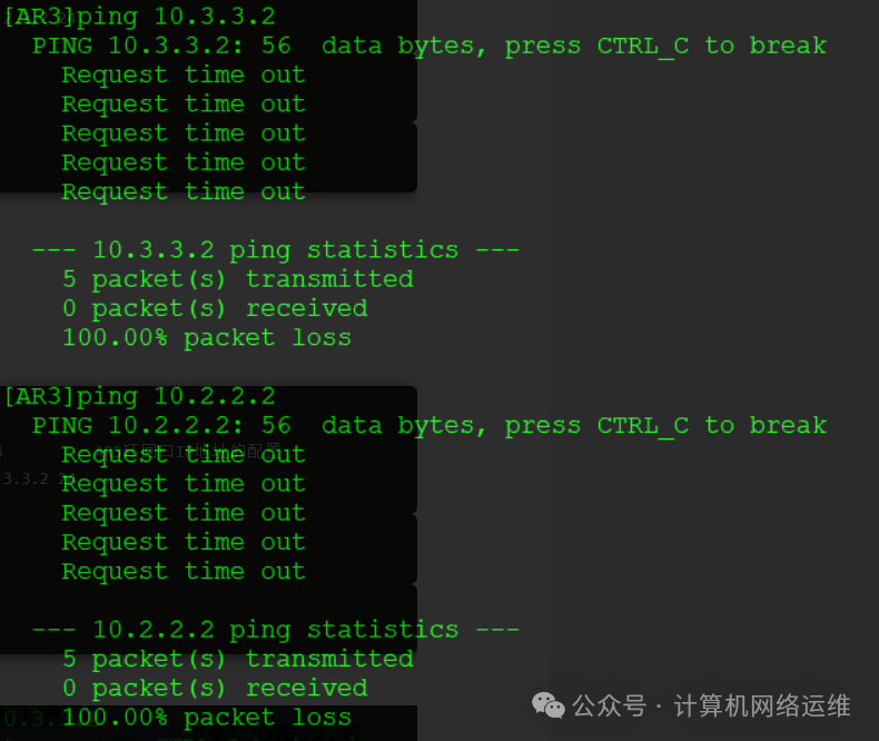
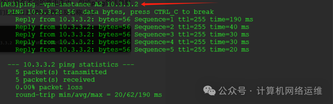
From the above two images, we can conclude that directly pinging AR5 and AR9 from AR3 is not possible, even though they are directly connected routes. This is because they are in different routing tables, and a simple ping defaults to the Public routing table. Therefore, when pinging the CE’s network segment from the PE, we need to include the corresponding vpn-instance name! On the CE side, we can ping directly!
[AR3]ping -vpn-instance A2 10.3.3.2 Ping 10.3.3.2 in VPN instance A2
🎏PE Device AR3 Connecting to CE Device AR5 Using ISIS Protocol!
[AR3]isis 1 vpn-instance A2          Bind ISIS process 1 to VPN instance A2
[AR3-isis-1]network-entity 49.0035.0000.0000.0003.00   Publish ISIS
[AR3-isis-1]is-level level-2       Set ISIS basic level to level 2
[AR3-GigabitEthernet0/0/1]isis enable 1   Enable ISIS process 1 on AR3's G0/0/1 port
🎏CE Device AR5 Connecting to PE Device AR3 ISIS Configuration
[AR5]isis   Enable ISIS (default process 1)
[AR5-isis-1]network-entity 49.0035.0000.0000.0005.00  Publish ISIS
[AR5-isis-1]is-level level-2   Set ISIS level to level 2
[AR5-GigabitEthernet0/0/0]isis enable 1   Enable ISIS protocol on this port
[AR5-LoopBack0]isis enable 1          Enable ISIS on the loopback interface
[AR3]display isis peer vpn-instance A2  View ISIS neighbors in VPN instance A2
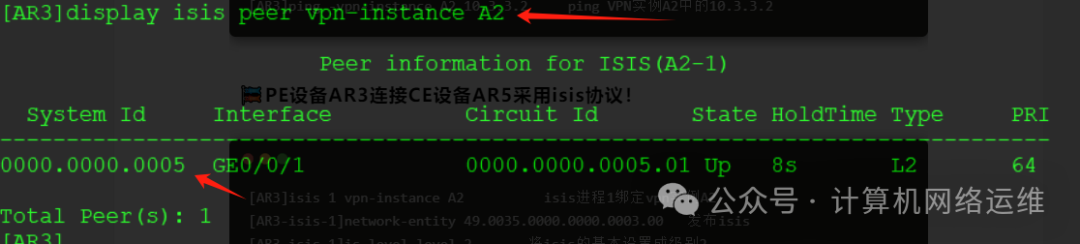
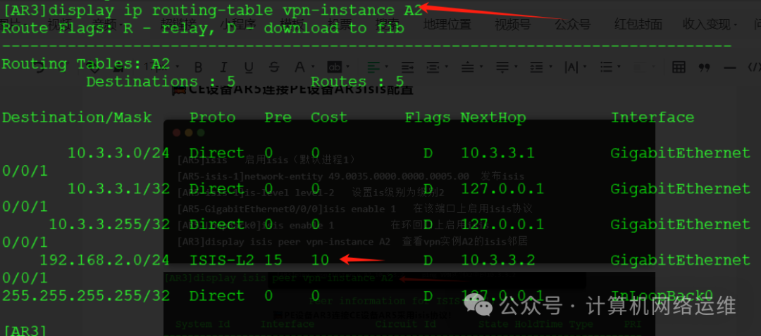
Checking the routing table reveals that AR3 has learned the loopback address 192.168.2.0 from AR5.
🎏CE Device AR5 Connecting to PE Device AR3 EBGP Configuration
[AR9]bgp 9    Enter BGP and set your AS number to 9
[AR9-bgp]peer 10.2.2.1 as-number 123   Specify EBGP neighbor 10.2.2.1, AS number 123 (if EBGP specifies AS, it is the AS number used by the PE in the public network)
[AR9-bgp]network 192.168.2.0 24    Announce the 192.168.2.0 24 network segment
🎏PE Device AR3 Connecting to CE Device AR9 Using EBGP Protocol!
[AR3]bgp 123   Enter BGP and set your AS number to 123
[AR3-bgp]ipv4-family vpn-instance B2  IPV4 address group, BGP bound to VPN instance B2
[AR3-bgp-B2]peer 10.2.2.2 as-number 9   Specify EBGP neighbor address 10.2.2.2 AS number 9
[AR3-bgp]router-id 3.3.3.3    Create BGP router ID as 3.3.3.3
[AR3]display bgp vpnv4 vpn-instance B2 peer      View BGP neighbors in VPN instance B2
[AR3]display ip routing-table vpn-instance B2    View BGP VPN V4 routing table for VPN instance B2 (instance 2 learned BGP routes)
[AR3]display ip routing-table vpn-instance B2    View routing table for VPN instance B2
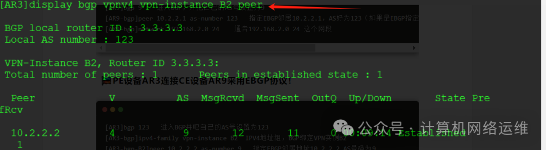
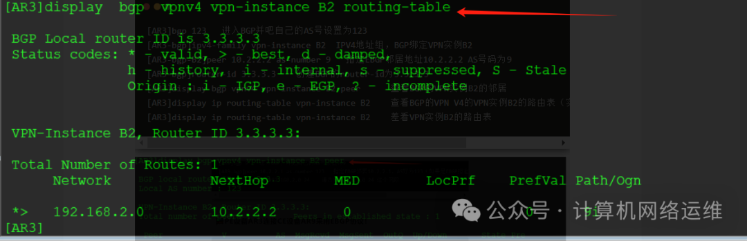
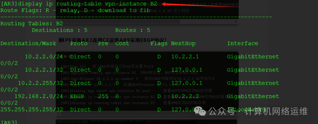
From the above images, we can see that AR3 has learned the BGP route 192.168.2.0 in VPN instance B2! AR3 has established an EBGP neighbor relationship in VPN instance B2! Thus, the configuration of virtual routing and vpn-instance is complete. In the next issue, we will explain MPLS-VPN’s MP-BGP
Click the card above to follow us👆
Reply with the corresponding number to receive Huawei network engineering study materials