01
Application Function Introduction
1.1
•
What is an Interrupt
An interrupt is a mechanism that temporarily halts the CPU’s normal execution of the main program to handle urgent tasks, after which it returns to the previously paused program, as illustrated below.
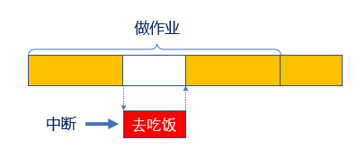
Figure 1.1 Interrupt Diagram
In digital power and motor control systems, the significance of interrupts is particularly important, mainly reflected in the following aspects:
-
Real-time response and control: Interrupts ensure the system can quickly respond to critical events (such as voltage, current, speed, position feedback, etc.). For example, in a motor control system, sensor signals or encoder pulses can be captured via interrupts, allowing for precise control of motor position and speed.
-
Improving system efficiency: In motor control and power management systems, handling a large amount of sensor data is often necessary. Without interrupts, the system may resort to “polling” (constantly checking if a signal has changed), which wastes CPU resources. By using interrupts, the system can process only when significant events occur, greatly enhancing efficiency.
-
Precise closed-loop control: Motor control systems often require closed-loop control, such as speed or position control based on PID algorithms. Interrupts allow the system to capture feedback signals in real-time and adjust based on the difference between set values and actual feedback. In power control, interrupts can be used to precisely adjust output voltage or current, maintaining stable output.
-
Energy saving and power management: In power control systems, interrupts can also be used for energy-saving management. For example, in low-load or idle states, the system can enter low-power mode via interrupts and be awakened by significant events (such as load changes). This is particularly useful in battery-powered devices, helping to extend battery life. In motor control, interrupts can also be used to precisely adjust the motor’s duty cycle, optimizing power usage.
-
Multitasking parallel processing: Through interrupts, motor and power control systems can handle multiple tasks simultaneously. For instance, in motor control, the system can handle speed feedback, position feedback, and safety protection via different interrupts; in power management, it can process multiple input power statuses or load situations. The nested priority design of interrupts ensures that the system can prioritize critical tasks without being delayed by lower-priority tasks.
The significance of interrupts: Efficiently handling urgent tasks without continuously occupying CPU resources.
1.2
•
NVIC
2.2.1
•
Basic Concept of NVIC
NVIC (Nested Vectored Interrupt Controller) is the interrupt controller in MCUs (Microcontroller Units) responsible for managing external and internal interrupts. It supports interrupt nesting, allowing high-priority interrupts to interrupt lower-priority ones, thereby enhancing system responsiveness. NVIC uses a vector table to manage interrupts, with each interrupt source corresponding to an Interrupt Service Routine (ISR). Users can set priorities for interrupts and dynamically enable or disable specific interrupts to ensure the safety of critical code sections. Additionally, NVIC manages interrupt states, facilitating developers in monitoring and controlling interrupt behaviors. These features make NVIC crucial for designing efficient, real-time embedded applications.
TAE32G5800 has 85 maskable interrupt channels (excluding 16 interrupt lines of Cortex™-M4) and 16 programmable priorities (using 4-bit interrupt priorities).
1.2.11
•
What is an Interrupt Vector Table
Defines a fixed memory area aligned to 4 bytes, storing the starting addresses of various interrupt service function programs, as shown in the figure below.
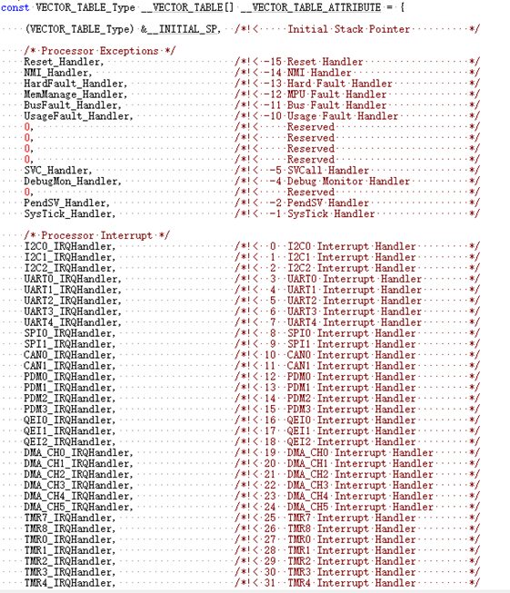
Figure 1.2 TAE32G5800 Interrupt Vector Table
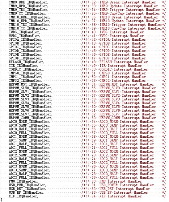
Figure 1.3 TAE32G5800 Interrupt Vector Table
The interrupt vector table is defined in the startup file, and when an interrupt occurs, the CPU automatically executes the corresponding interrupt service function, as shown in the figure below.
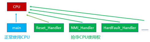
Figure 1.4 Interrupt Vector Diagram
1.2.3
•
Basic Concept of Interrupt Vector Priority
Interrupt priority is a mechanism used to determine how the processor responds when multiple interrupts occur simultaneously. Each interrupt has a priority value, with lower values indicating higher priority. TAE32 supports the configuration of preemptive priority and response priority, allowing high-priority interrupts to interrupt low-priority ones. Additionally, priorities can be grouped, allowing interrupts within the same group to be sorted based on response priority. This flexible priority management ensures that the system can effectively handle critical tasks in real-time applications while avoiding interference from lower-priority interrupts, thus enhancing system reliability and performance. The classification of interrupt priorities is as follows:
-
Preemptive priority (pre): High preemptive priority interrupts can interrupt low preemptive priority interrupts.
-
Response priority (sub): When preemptive priorities are the same and interrupt signals occur simultaneously, the one with higher response priority is executed first, while the one with lower response priority is executed later, but they cannot interrupt each other.
-
Natural priority: Priority of the interrupt vector table.
Note: A smaller value indicates a higher priority. When both preemptive and response priorities are the same, the one with a higher natural priority executes first.
1.2.4
•
How TAE32 Interrupt Priority is Grouped
TAE32 is a mixed-signal microcontroller based on the Arm® Cortex®-M4 architecture, with interrupt priority grouping as shown in the following table.
Table 1.1 Interrupt Priority Group Configuration
|
Priority Group |
AIRCR[10:8] |
IPRx bit[7:4] Allocation |
Allocation Result |
|
0 |
111 |
None:[7:4] |
0 bits preemptive priority, 4 bits response priority |
|
1 |
110 |
[7]:[6:4] |
1 bit preemptive priority, 3 bits response priority |
|
2 |
101 |
[7:6]:[5:4] |
2 bits preemptive priority, 2 bits response priority |
|
3 |
100 |
[7:5]:[4] |
3 bits preemptive priority, 1 bit response priority |
|
4 |
011 |
[7:4]:None |
4 bits preemptive priority, 0 bits response priority |
2 bits preemptive priority and 2 bits response priority. This means that the preemptive priority can be set to levels 0-3, and the response priority can also be set to levels 0-3, and so on. Generally, in a project, the interrupt priority grouping is set only once.
Example of TAE32 interrupt priority (assuming priority grouping is 2), as shown in the following table.
Table 1.2 Example of Interrupt Priority
|
Number |
Natural Priority |
Corresponding Peripheral Interrupt |
Preemptive |
Response |
Execution Order |
|
3 |
10 |
UART0 |
2 |
1 |
2 |
|
6 |
13 |
UART3 |
3 |
0 |
4 |
|
28 |
35 |
TMR1 |
2 |
0 |
1 |
|
-1 |
6 |
Systick |
3 |
0 |
3 |
TMR1 and UART0 can interrupt: UART3 and Systick interrupts to gain priority execution.
1.2.5
•
Using TAE32 NVIC
The working principle of NVIC is illustrated in the figure below.
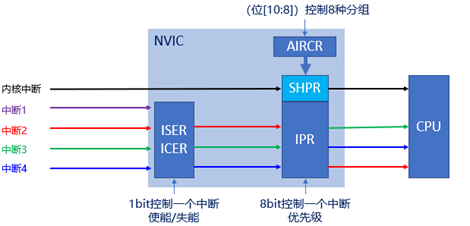
Figure 1.5 NVIC Working Principle
-
Set interrupt grouping: SCB->AIRCR[10:8], LL_NVIC_SetPriorityGrouping(uint32_t PriorityGroup), where the parameter affects the register AIRCR[10:8]. For interrupt grouping configuration, please refer to Table 1.1.
-
Set interrupt priority: NVIC->IPRx bit[7:4], LL_NVIC_SetPriority(IRQn_Type IRQn, uint32_t PreemptPriority, uint32_t SubPriority), with parameters being the interrupt vector number, preemptive priority, and response priority.
-
Enable interrupt: NVIC->ISERx, LL_NVIC_EnableIRQ(IRQn_Type IRQn), with the parameter being the interrupt vector number.
1.3
•
How to Use TAE32 Interrupts
The general steps for configuring external interrupts are similar. Here, we take the timer interrupt as an example. After opening the TAE32G5800 TMR example and configuring all the TMR examples, we start configuring interrupts with the following steps:
-
Set interrupt grouping: Use LL_NVIC_SetPriorityGrouping, default is 2 groups, already configured during LL library initialization.
-
Set interrupt priority and enable interrupt: Use LL_NVIC_SetPriority, LL_NVIC_EnableIRQ
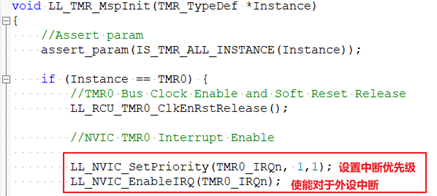
Figure 1.6 Setting Interrupt Priority and Enabling Interrupt
3. Set hardware interrupt service function: Write TMR0_IRQHandler, the interrupt service function, check the flag, and clear the interrupt flag! For convenience, customers can directly use the LL library’s interrupt handling common function (similarly for other peripherals) LL_TMR_IRQHandler, as shown in the figure below:
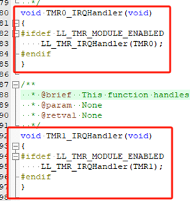
Figure 1.7 Calling the LL Library’s Common Interrupt Service Function
4. Write the LL library interrupt handling callback function, such as the “update overflow interrupt callback function” for TMR. Other callback functions can also enter LL_TMR_IRQHandle to query the corresponding interrupt callback function, as shown in the figure below.
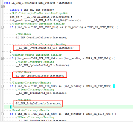
Figure 1.8 Finding the Interrupt Callback Function
Write the corresponding interrupt callback function. This interrupt callback function can be redefined, and users need to redefine the corresponding interrupt callback function. According to the interrupt flag, handle various interrupt transactions of the peripheral. When a specific interrupt occurs, the MCU will execute this function, as shown in the figure below.
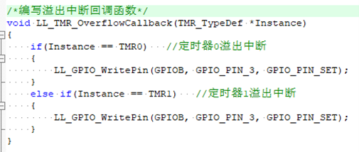
Figure 1.9 Writing the Corresponding Interrupt Callback Function
1.4
•
Introduction to LL Library Interrupt Callback Mechanism
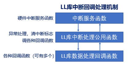
Figure 1.10 LL Library Interrupt Callback Mechanism Diagram
1.5
•
Verifying Preemptive Priority
This chapter uses TMR to verify that high preemptive priority can interrupt low preemptive priority. Configure TMR7 and TMR8, with TMR7 timing 100ms and TMR8 timing 150ms, with preemptive priorities of 2 and 1 respectively, and enable the relevant interrupts. The code listing is as follows.
int main(void){ SystemClock_Config(); //Clock initialization LL_Init(); //LL library initialization GPIO_init(); //GPIO initialization base_timer_init(TMR7,10000-1,900-1,2); //TMR7 100ms timing, preemptive priority 2 base_timer_init(TMR8,10000-1,1350-1,1); //TMR8 150ms timing, preemptive priority 1 LL_TMR_Start_IT(TMR7); //Start TMR7 LL_TMR_Start_IT(TMR8); //Start TMR8 while (1){}}
void base_timer_init(TMR_TypeDef *Instance,uint16_t period,uint16_t prescaler,uint32_t PreemptPriority){ TMR_BaseInitTypeDef base_timer_init; //Timer configuration structure memset((void *)&base_timer_init, 0x00, sizeof(base_timer_init)); //Initialize this structure’s parameters to zero before calling this function, allowing it to be reused for initializing different timers /*Timer parameter configuration*/ base_timer_init.auto_preload_en = true; //Enable auto-reload feature base_timer_init.work_mode = TMR_WORK_MODE_CONTINUE; //Set work mode to continuous counting base_timer_init.period = period; //Auto-reload value base_timer_init.prescaler = prescaler; //Prescaler value base_timer_init.update_evt_en = true; //Enable update interrupt feature base_timer_init.update_evt_src = TMR_UPDATE_EVT_SRC_OV; //Set update interrupt trigger condition to overflow LL_TMR_Init(Instance); //Call LL library to enable timer clock and interrupt LL_TMR_Base_Cfg(Instance,&base_timer_init); //Configure timer parameters /*********************Set Interrupt Priority*******************/ if(Instance == TMR7) { LL_NVIC_SetPriority(TMR7_IRQn, PreemptPriority, 0); } else if(Instance == TMR8) { LL_NVIC_SetPriority(TMR8_IRQn, PreemptPriority, 0); } /****************Set Interrupt Priority********************/}
In the interrupt callback function, TMR7 (100ms interrupt) uses a while loop to pull PB3 high, while TMR8 (150ms) pulls PB3 low. This way, it visually verifies that the interrupt with a higher preemptive priority can interrupt the one with a lower preemptive priority. The code listing is as follows.
void LL_TMR_OverflowCallback(TMR_TypeDef *Instance){ if(Instance == TMR7) //TMR7 interrupt { while(1) { LL_GPIO_WritePin(GPIOB, GPIO_PIN_3, GPIO_PIN_SET); } } else if(Instance == TMR8) //TMR8 interrupt { LL_GPIO_WritePin(GPIOB, GPIO_PIN_3, GPIO_PIN_RESET);
}}
1.6
•
Logic Analyzer Preemption Mechanism
In the interrupt callback function, TMR7 executes a while(1) loop statement to repeatedly pull PB3 high, while TMR8 pulls PB3 low, verifying that TMR8 will interrupt TMR7’s interrupt program for preemption, pulling PB3 low and then returning to TMR7’s interrupt program to pull PB3 high, thus cycling. A logic analyzer captures the waveform of PB3 consistent with theory, as shown in the figure below.
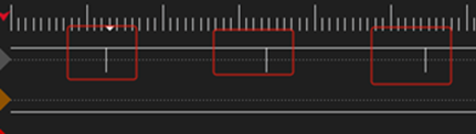
Figure 1.11 Logic Analyzer Waveform 1
Swapping the preemptive priorities of TMR7 and TMR8 will cause PB3 to remain high, because TMR7’s preemptive priority is higher than TMR8’s. When TMR7’s interrupt occurs, it executes the interrupt program with low preemptive priority, which cannot be preempted unless, as in the previous case, TMR8’s preemptive priority is higher than TMR7’s, at which point PB3 will change its level, as shown in the figure below.

Figure 1.12 Logic Analyzer Waveform 2
About Taiwei
ZhuHai Taiwei Electronics Co., Ltd. was established in 2019 and is a high-tech enterprise dedicated to the R&D of industrial-grade and automotive-grade core processor chips, committed to leading innovation in the domestic semiconductor industry, continuously innovating in fields such as industrial control, new energy power conversion, power quality monitoring and management, high-end power supplies, and servo systems, and continuously developing industrial-grade core processor chips to comprehensively replace foreign products, fully committed to providing customers with higher quality products and services.
For more information, please follow us
Phone: 0756-3666670
Website: www.tai-action.com
WeChat Official Account: Tai-action
Bilibili Video Account: Taiwei Electronics
Taobao Store: Search for “Taiwei Electronics”