Click the blue text above to follow us


IPv4 and IPv6 Headers
IP is the core protocol in the TCP/IP protocol suite, and all TCP, UDP, ICMP, and IGMP data is transmitted via IP datagrams. IP provides a best-effort, connectionless packet delivery service. The meaning of “best-effort” is that it does not guarantee that IP datagrams will successfully reach their destination. Although IP does not simply discard all unnecessary traffic, it does not provide guarantees for the data it attempts to deliver.
When certain errors occur, such as a router temporarily running out of buffer space, IP provides a simple error handling method: it drops some data. Any reliability must be provided by the upper layers, such as TCP. Both IPv4 and IPv6 use a best-effort basic delivery model.
Next, “connectionless” means that IP does not maintain any connection state information related to datagrams in the network unit, and each datagram is processed independently of other datagrams. This also means that IP datagrams may not be delivered in order. If a host sends two consecutive datagrams to the same destination, each datagram can be routed independently, taking different paths, and the order in which they arrive may not be the order in which they were sent.
Moreover, IP datagrams may also encounter other issues; they may be duplicated during transmission, and their content may change, leading to errors. Therefore, some upper-layer protocols need to handle these potential issues to provide error-free delivery.
IPv4 and IPv6 Datagram Structure
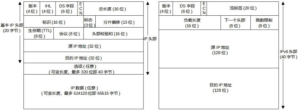
The header size of an IPv4 datagram is variable, while the header size of an IPv6 datagram is fixed at 40 bytes. Let’s look at the specific field analysis:
Version: Used to specify the different versions of the IP protocol, with IPv4 being 4 and IPv6 being 6. Apart from the version field’s location being the same, the two protocols differ in all other aspects, thus these two protocols cannot directly interoperate; hosts or routers must handle IPv4 or IPv6 separately (or both, referred to as dual-stack).
Internet Header Length (IHL): Used to indicate the number of 32-bit words in the IPv4 header, including any options. Since it is a 4-bit field, the IPv4 header is limited to 15 32-bit words, or 60 bytes.
Type of Service (ToS): Used to specify the type of communication. The first 6 bits (DS field) are known as the Differentiated Services field, and the last 2 bits (ECN) indicate congestion notification or marking, differentiating between different types of datagrams, such as real-time datagrams (for applications like IP telephony) and non-real-time traffic (like FTP). Congestion notification and marking can provide specific levels of service, determined and configured by network administrators on routers.
Total Length: This is the length of the datagram in bytes. Using this field and IHL, one can determine where the data portion of the IPv4 datagram begins and the length of the data. The maximum length of an IPv4 datagram (including the header) is 65535 bytes, while the maximum length of IPv6 is limited to 64KB. IPv6 also supports an option for oversized datagrams, theoretically allowing a single packet to support a maximum length of 4GB. In general, datagrams rarely exceed 1500 bytes, as this length allows the IP datagram to be carried in the maximum capacity Ethernet frame’s payload field.
Ethernet pads short frames to a minimum length (64 bytes). Although the minimum effective payload for Ethernet is 46 bytes, an IPv4 datagram may be smaller (20 bytes). Without the total length field, IPv4 implementations would not know if a 46-byte Ethernet frame is an IP datagram or a padded IP datagram. Additionally, hosts do not need to receive IPv4 datagrams larger than 576 bytes. Many applications using UDP for data transmission limit the data size to 521 bytes to avoid the 576-byte IPv4 limitation.
Identification: The sending host increments an internal counter by 1 each time it sends a datagram and copies that counter value into the IPv4 Identification field. This works in conjunction with the other two fields, Flags and Fragment Offset, for packet fragmentation operations, which will be detailed in a future blog related to IP fragmentation.
Time to Live (TTL): Used to set a limit on the number of routers a datagram can pass through, ensuring that the datagram does not loop indefinitely in the network. The sender initializes it to a certain value (suggested as 64 by [RFC1122], but 128 or 255 are also common), and each router decrements this value by 1 when forwarding the datagram. When this field’s value reaches 0, the datagram is discarded, and an ICMP message is sent to notify the sender.
Protocol: Used to indicate the type of data in the payload of the datagram, which is the transport layer protocol. When the datagram reaches its destination, it is used to determine which transport layer protocol (like TCP or UDP) should handle it.
Header Checksum: Used to help routers detect bit errors in the received IP datagram’s header. Note that it only checks the header bits, not the entire message. This field exists only in IPv4 and not in IPv6. The checksum is calculated by treating every 2 bytes in the header as a number and summing them using one’s complement arithmetic; details will be provided later.
Source and Destination IP Addresses: When a source generates a datagram, it inserts its IP address into the Source IP field and the intended final destination address into the Destination IP field. Typically, the source host determines the destination address via DNS lookup.
Having introduced the shared header fields of IPv4 and IPv6, let’s now look at the extension header fields of IPv6:
Flow Label: Used to identify a flow of datagrams, allowing for priority to be given to certain datagrams in that flow, or it can be used to give higher priority to datagrams from certain applications (like IP voice) over others (like SMTP email).
Payload Length: This is the length of the payload, a 16-bit value treated as an unsigned integer that indicates the number of bytes following the fixed 40-byte header of the IPv6 datagram.
Next Header: This field identifies which protocol the content of the datagram should be delivered to (e.g., TCP or UDP), which functions the same as the Protocol field in IPv4.
Hop Limit: Each router forwarding the packet decrements the value in this field by one. If the hop limit count reaches 0, the datagram is discarded, functioning the same as the Time to Live (TTL) field in IPv4.
Internet Checksum
The IPv4 header checksum differs from the cyclic redundancy check (CRC) introduced in the link layer. To compute the IPv4 checksum for the output datagram, the checksum is first set to 0. IPv4 calculates the 16-bit one’s complement sum of the header, which is stored in the checksum field. One’s complement addition can be performed using carry-around addition: when traditional (two’s complement) addition produces a carry, it is added as a binary 1 to the high order.
When an IPv4 datagram is received, a checksum is calculated for the entire header, including the value of the checksum field itself. If the datagram is error-free, the calculated checksum value should be 0 (the one’s complement of the value FFFF). The following example illustrates this in detail:
Assuming an IPv4 header is: E3 4F 23 96 44 27 99 F3 [00 00], where the value in the brackets is the checksum.
The initial checksum value is set to 0, as shown in the example;
Then, in 16-bit units, they are added two by two, so the above example yields: E34F + 2396 + 4427 + 99F3 = 1E4FF;
If the result exceeds 0xFFFF, the high 16 bits are added to the low 16 bits, yielding 0xE4FF + 1 = E500;
Then, the value is inverted, yielding ~ (E500) = 1AFF, which is the value that should be in the checksum field of the sent message;
When the receiver gets the datagram, if it is normal, its header should be: E3 4F 23 96 44 27 99 F3 1A FF.
At this point, the first 16 bytes remain unchanged, yielding E500, and the checksum value 1AFF is added to E500;
If the result equals FFFF, the datagram is normal and error-free.
DS Field and ECN
In the Internet protocol, it can also be said that routers may not simply forward datagrams based on first-come-first-served principles, but may prioritize forwarding based on the service type, depending on the network administrator’s configuration policy for the routers.
The numbers in the DS field are called Differentiated Services Code Points (DSCP). Generally, if a datagram has an allocated DSCP, that DSCP remains unchanged during the delivery process through the network infrastructure. However, certain policies may cause a DSCP in a datagram to change during delivery, meaning that the value of the DS field may be modified due to the service policies of the network infrastructure provider.
When a datagram passes through a router with internal queuing, the two bits in the header used for ECN mark the congestion identifier. In other words, when a router capable of ECN sets these two bits while forwarding packets. This design aims to allow some protocols (like TCP) to detect marked packets upon receipt and notify the sender, which can then reduce the sending rate to mitigate congestion before the router is forced to drop traffic due to overload.
The structure of the ToS service type field and its functions and services:
Although the original ToS (Type of Service) was not widely supported, the DS field structure still provides some compatibility, and the DS field somewhat continues and improves the relevant functions of ToS. First, let’s understand the structure of ToS: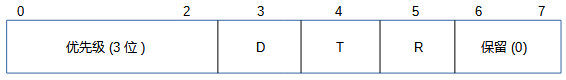
The priority subfield is used to indicate which packets have higher priority. The D, T, and R subfields represent delay, throughput, and reliability, respectively. If these field values are 1, they indicate low delay, high throughput, and high reliability.
The range of priority values is 000 (normal) to 111 (network control), indicating increasing priority levels. They are based on a scheme called Multi-Level Priority and Preemption (MLPP). Below are the specific priority levels of the ToS priority subfields:
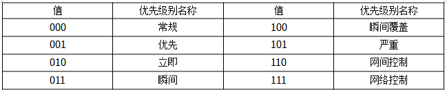
In simple terms, the higher the value of the priority, the higher the order of forwarding for the datagram, meaning the router will forward it sooner. DTR describes the transmission performance of the router, and the values of the priority subfields determine the order of forwarding. DTR is used for congestion control at the upper layer (transport layer).
The structure of the DS field and ECN field and their functions and services:
When defining the DS field, the values of priority have been defined in [RFC2474] to ensure effective compatibility. The 6-bit DS field stores DSCP, supporting 64 code points. Specific DSCP values can notify routers to forward or specially process received datagrams. Different types of forwarding treatment are represented as per-hop behavior (PHB), so DSCP values effectively inform routers which PHB is used for the datagram. The default value for DSCP is usually 0, corresponding to normal best-effort Internet traffic. The 64 possible DSCP values are divided into different uses. Let’s first look at the structure of the DS field and ECN:
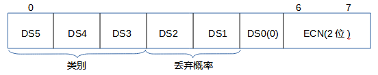
Here, we focus on DSCP, which is the 6 bits of the SD field, of which 5 bits are standard, indicating that when the received datagram should be forwarded, it can be processed by a compatible internal queuing router according to its priority level (i.e., PHB). DSCP values are divided into three pools: standard priority levels, experimental/local use (EXP/LU) priority levels, and experimental/local use priority levels intended for standardization (*), as detailed in the following format:
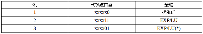
Through the code point prefixes above, we can distinguish which standard forwarding priority is adopted by the datagram. However, this is generally not our primary concern. The first thing to understand is how the DS field is compatible with the previous ToS (Type of Service) priorities. In the previously introduced ToS, its priority is determined by the first 3 bits, while in DS, it uses a code point in the form xxx000 to support some of the ToS priority fields. For specific compatibility with which priorities, please refer to [RFC0791].
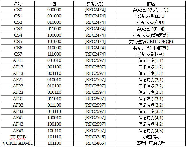
Now let’s look at the specific code points (binary values) for DSCP standard priorities and traffic categories:
Default (BE): 000 000, indicating best-effort priority, which can be considered the lowest priority and a special CS, meaning the priority subfield 000 in ToS is also the lowest priority;
-
Class Selector (CS): aaa 000, used for compatibility with the ToS priority subfield.
-
Assured Forwarding (AF): aaa bb0, a priority type defined by the DSCP standard;
-
Expedited Forwarding (EF): 101 110, a priority defined by the DSCP standard for carrying voice traffic, as voice requires low latency and low packet loss rates. It is second only to protocol messages in importance and can be considered a special AF;
Here, we need to focus on Assured Forwarding (AF) traffic categories. However, it is important to note that Assured Forwarding does not guarantee that the datagram will be forwarded; rather, it has two mechanisms to ensure forwarding relative to the default 000000. One is that the forwarding priority is determined by the first three bits of the five code points, and the other is that the discard priority is determined by the last two bits of the five code points, as the sixth code point is used to indicate standard policies.
The priority of the DS field (DSCP priority) can produce seven priority levels based on the first three binary bits, as 000 is the default best-effort. Thus, from 001 to 111, there are only seven levels. The larger the binary value, the higher the priority represented, with 111 being the highest priority, although it has not yet been standardized and is reserved.
The discard priority of the DS field (DSCP discard priority) can produce four priority levels based on the last two binary bits, where 00 to 11 can represent four levels. The larger the binary value, the higher the priority relative to the same forwarding priority. The higher the binary value of the discard priority, the sooner it will be discarded (but this discard will definitely be more reliable than the default 000000 service category, as the first to be discarded will be the default 000000 datagram).
These different forwarding priorities and discard priorities constitute different DS service types. The higher the forwarding level, the lower the discard level, and the service fees will vary accordingly, depending on the service provider’s (ISP) offerings.
On the other hand, different service types are generally used to support different data flows. There are a total of seven forwarding priorities and eight application types, including: 7 reserved (111), 6 reserved (110), 5 voice (101), 4 video conferencing (100), 3 call signaling (011), 2 high-priority data (010), 1 medium-priority data (001), and 0 best-effort data (000). Service providers will typically offer traffic services based on different application types, and combined with discard levels, will produce different service fee standards. Below is a table of different standard service types, corresponding DS field values, and related descriptions:
IP Options
IP supports several options that can be chosen for datagrams. In the early stages of IPv4, the Internet scale was small, and there were fewer threats from malicious users. Due to the limitations on IPv4 header size and related security issues, most options have been removed or altered in IPv6 and are no longer part of the basic IPv6 header but are placed in one or more extension headers following the IPv6 header.
When an IP router receives a datagram containing options, it usually needs to process the datagram specially. In some cases, although IPv6 routers can handle extension headers, many headers are designed to be processed only by end hosts. In routers, datagrams with options or extensions are not forwarded as quickly as ordinary datagrams.
IPv4 Options
Information about IPv4 options can be found in related descriptive RFCs. This complete list is regularly updated and can be viewed online at [IPPARAM]. The range of options is always bounded by 32 bits, and if there are not enough characters, they are padded with 0s, ensuring that the IPv4 header is always a multiple of 32 bits (as required by the IHL field).
If options exist, they immediately follow the basic IPv4 header in the IPv4 packet.
Option Identifier (8 bits): Options are identified by an 8-bit type field, which is subdivided into three subfields:
Copy (1 bit): When the value is 0, it indicates that it is only copied in the first fragment; when the value is 1, it indicates that it is copied to all fragments;
Class (2 bits): 00 indicates datagram control, 01 indicates reserved, 10 indicates debugging and management, 11 indicates reserved.
Number (5 bits): Various options are identified by a 5-bit number. For example, 00000 is the identifier for the end of options, 00001 is the identifier for the no-operation option (used for padding), 00011 is the identifier for loose source routing (the sender lists the routers traversed during forwarding, with loose meaning that it can include other waypoints), 00100 is the identifier for timestamps (used to record the date and time of the source and destination of the packet), 00111 is the identifier for recording routes (recording the routers traversed in the packet’s header), and 01001 is the identifier for strict source routing (the sender lists the routers traversed during forwarding, with strict meaning that all waypoints must be traversed in order). More option identifiers can be referenced in the related option documentation at [IPPARAM].
Option Length Field (8 bits): Indicates the total length of the option. Most options have variable lengths, but single-byte options do not require a length field. Single-byte options only have two identifiers: 00000 for the end of options and 00001 for the no-operation option; other options require a length field;
Option Value: This records some data corresponding to the option.


Disclaimer: Content sourced from the internet, thanks to the contributors. If there is any infringement, please contact us for removal.