
For training, consulting, or project development, please contact 【Thought】
Readers of this public account must be familiar with the CAN communication protocol. Have you ever wondered how these signals are implemented in the communication protocol within the Electronic Control Unit (ECU) when collecting CAN bus signals and analyzing data? This content introduces how to implement the CAN bus communication protocol in a C language environment. A basic understanding of C language is required, and I hope everyone can stick with it until the end; you will definitely gain something.
According to the previous article “CAN Bus (J1939) Quick Guide【1】”, there are three very important pieces of information in the CAN communication protocol: message ID, data field, and parsing with offsets. The first step in implementing the communication protocol is to define a struct for the message.
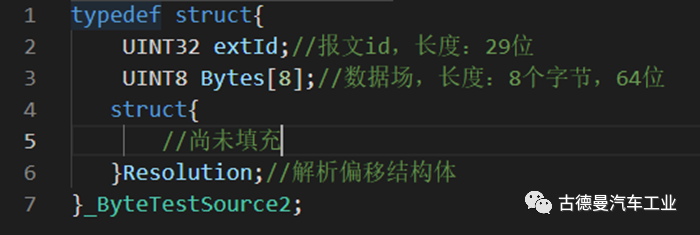
⚪ Defining Message ID
The example used here is based on the extended ID, with an ID length of 29 bits. Since C language does not have a 29-bit data type, a 32-bit data type UINT32 is used. For standard IDs, a 16-bit data type UINT16 is sufficient.
Tip: Data Types
Standard C language does not have variables like UINT32, UINT16, etc.; these are predefined in macros based on the type of chip used. For example, UINT32 for a 16-bit system corresponds to “unsigned long” in C language, while for a 32-bit system, UINT32 corresponds to “unsigned int”.
⚪ Defining Data Field
Use the UINT8 data type to define an array of eight bytes to store data field information.
⚪ Defining Parsing and Offset Struct
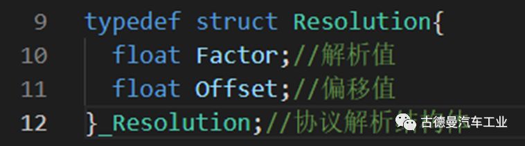
Additionally, define another struct to store offsets and parsing values. As shown in the image, it contains two float-type data.
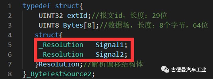
In our message struct, instantiate the parsing information for each signal. The red part in the image is only to illustrate how to call the [Parsing and Offset] struct, and we will later import our actual example information.
CAN data frames contain a 64-bit data field, and the matrix is used to define how the data field is divided. This part reflects the starting position and data length of each signal in the communication protocol.
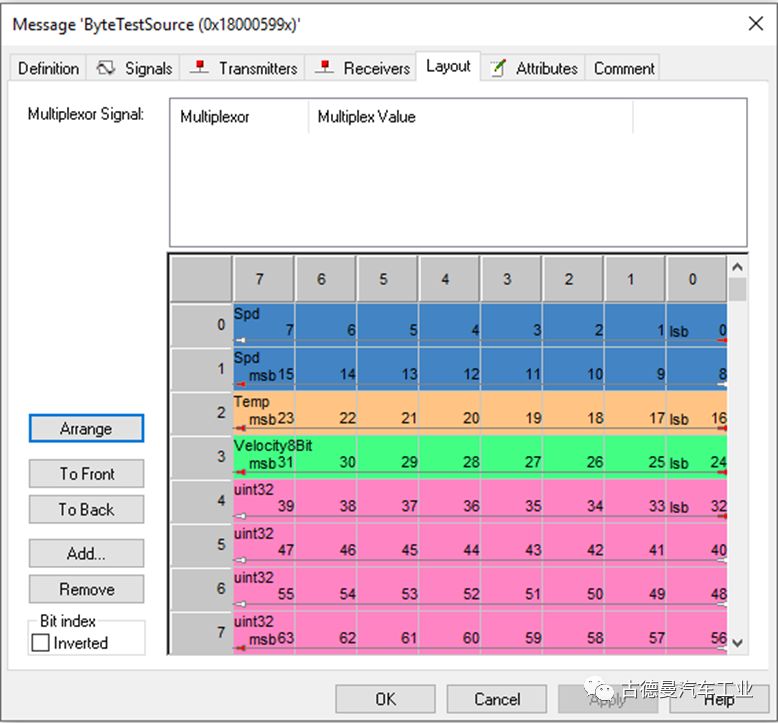
This is an example of a matrix created by 【Thought】 using Vector CANdb++, referred to as [Example One]. This example includes a 16-bit data, two 8-bit data, and one 32-bit data, totaling a length of 64 bits. The data bits are aligned without any gaps, which is quite perfect. However, practical applications are not always that beautiful.
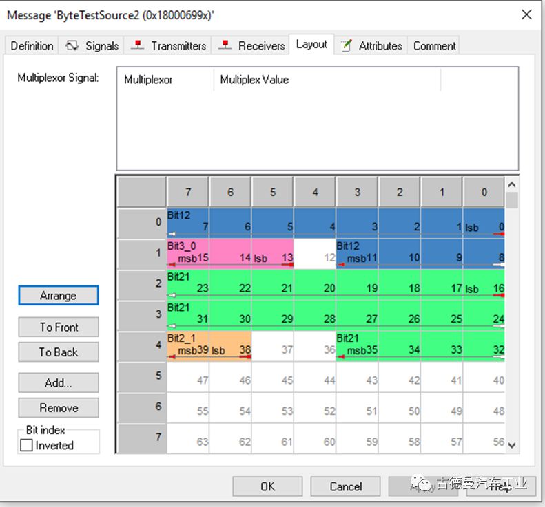
The above image shows another matrix defined by 【Thought】, referred to as [Example Two]. This matrix is quite peculiar, containing a 12-bit data, a 21-bit data, a 3-bit data, and a 2-bit data, with gaps between the data, leaving 24 bits of the data field unused.
The concept of unions is relatively obscure in C language; 【Thought】 was not very clear about what unions are used for before encountering the CAN protocol stack. Therefore, let’s introduce this concept first.
A union allows several variables to share the same memory location, saving different data types and variable lengths at different times. In a union, all members share a common space, and only one member variable’s value can be stored at a time. When a union is declared, the compiler automatically generates a variable whose length (in bytes, where a byte is 8 bits) is a multiple of the length of the longest data type in the union.
Returning to our CAN message data field, it consists of 8 one-byte memory spaces. Each message redefines this area based on its matrix information.
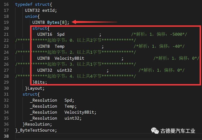
This code segment is from [Example One], using a union to describe matrix information. The defined union can be read and written through byte array (Bytes) data, as well as through bit-defined structure data (Bits) variables. The [Parsing and Offset] section also instantiates the structure for assignment during later initialization.
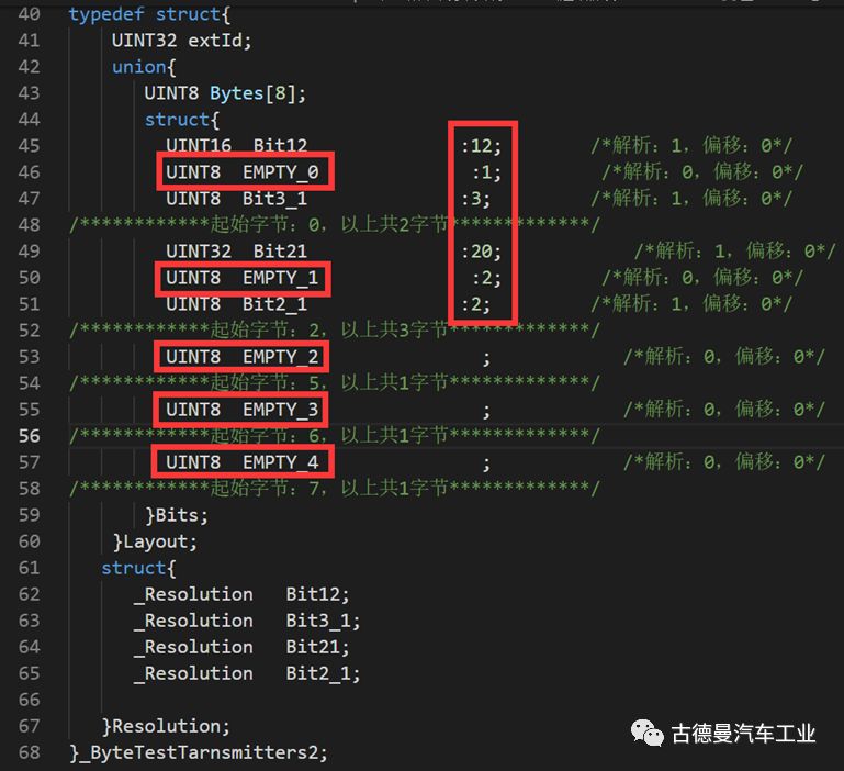
[Example Two] has unaligned data bits and gaps, making it a bit more complicated to process. First, we need to handle data lengths that are not commonly 8, 16, or 32. For example, the first data is a 12-bit data, so we define a UINT16 data using [UINT16 Bit12:12;] to specify that the effective data length is only 12 bits. Then, we need to handle the gaps, as shown in the matrix above. The 12th, 36th, and 37th bits are gaps, so we define a UINT8 data type to fill the gaps. In this example, [UINT8 EMPTY_1:2;] is used to define the gap length. It is important to prioritize data alignment to ensure the automated handling of byte order, which can be quite troublesome and will be discussed in dedicated content later.
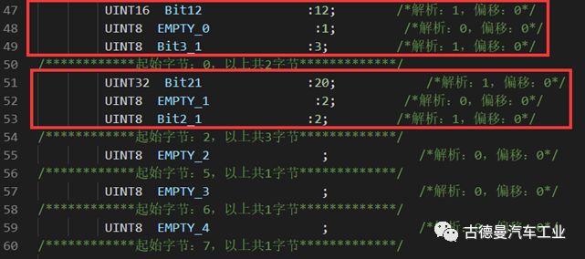
After filling the gaps, the length of the data block must be a multiple of 8 to achieve the alignment effect shown in the image. In fact, this union method is applicable to most communication protocols, such as TCPIP, 485, RS232, etc.
The above has introduced how to define the communication protocol in a struct; before truly using it, we need to instantiate the struct and initialize the data.

Instantiate the variable based on the previously created struct name.
The data initialization is sequentially as follows:
-
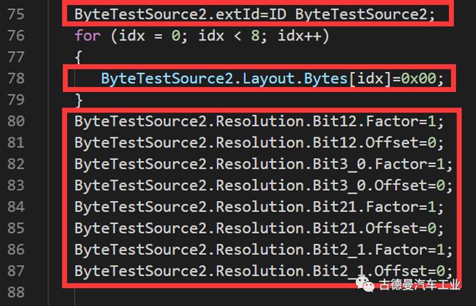
Assign a value to the message ID, which is defined earlier using macro definitions;
-
Fill all 64 bits of the data field with 0;
-
Assign values to the parameters of the parsing offset struct; padding bits do not require defined parsing offset parameters;
This time, 【Thought】 has selected two examples, one for sending and one for receiving, which can effectively illustrate parsing and encoding.
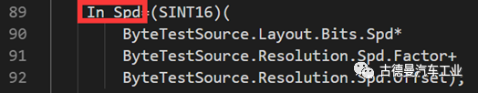
For example, to parse the Spd signal, the red box on the left shows the BSW->ASW interface variable, which directly accesses the Spd variable under the union in the struct, and calculates the actual value of Spd using the parsing and offset values from the parsing offset struct. For information on how to create the ASW and BSW interfaces, please refer to the article “Simulink Code Generation Application Tutorial” from this public account.
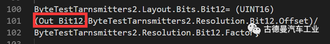
For sending messages, encoding processing is needed. The red box shows the ASW->BSW interface variable, which performs calculations with the interface variable and the parsing offset struct’s parsing values and offsets to obtain the data to be sent under the union in the message struct. This calculation is the inverse of the parsing calculation above.
So far, 【Thought】 has introduced how to implement the CAN bus message structure in C language, as well as data operations such as initialization, parsing, and encoding. Due to space limitations, the byte order issues between Freescale and Intel and interface automatic generation technology will be discussed in future articles.

■ Simulink Code Generation Improvement Tutorial
■ S-Function Application Example
■ C# from the Perspective of Automotive Engineers
■ Data Collection and Processing of Working Condition Road Spectrum
■ Secrets of Fuel Saving in Hybrid Power – Engine Universal Characteristics
■ AVL-CRUISE Pure Electric Simulation Strategy Improvement Tutorial
■ AVL-CRUISE Pure Electric Model Simulation Strategy■ Simulink Code Generation Application Tutorial
■ Simulink Code Generation Basic Experience Tutorial
■ Fuel Cell Vehicle (FCHEV) Power Economy Modeling and Simulation