
Select the appropriate current measurement range based on the size of the current to be measured, and insert the red probe into the “A” current jack. When measuring DC, the red probe (inserted into the current jack) should contact the higher voltage side, and the black probe should contact the lower voltage side. The forward current flows into the multimeter from the red probe and out from the black probe. If the size of the current to be measured is unclear, first use the maximum range for measurement, then gradually decrease the range for precise measurement.
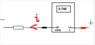 Connection circuit diagram for measuring current (i is the current)
Insert the red probe into the “V/Ω” jack, select the appropriate voltage measurement range based on the size of the voltage, connect the black probe to the circuit “ground” terminal, and the red probe to the point in the circuit to be measured. It is particularly important to note that digital multimeters measure AC voltage at low frequencies (45-500Hz); for mid-to-high frequency signals, the voltage amplitude should be measured using an AC millivolt meter.
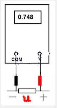 Connection circuit diagram for measuring voltage (u is the voltage)
Measuring resistance is relatively simple. Insert the red probe into the “V/Ω” jack and the black probe into the “com” jack. Select the appropriate resistance range based on the size of the resistance. Connect the red and black probes to both ends of the resistor and observe the reading. Importantly, when measuring in-circuit resistance (resistors on a circuit board), ensure the circuit power is turned off to avoid reading fluctuations. Avoid measuring current or voltage with the resistance setting (especially AC 220V); otherwise, the multimeter may be damaged. When testing in-circuit, ensure there are no parallel branches across the resistor. When selecting a high resistance range (e.g., measuring a 10M resistor), short the two probes first; the displayed value may be 1M. After each measurement, subtract this value to get the actual resistance (the error will be larger at higher resistance ranges).
Set the function and range switch to the buzzer mode, and test the probes at the respective points. If there is a short circuit, the buzzer will sound. This method can be used to check the continuity of circuit lines.
Note: A buzzer sounding does not necessarily indicate a short circuit between two points; it may also sound if the resistance between the two points is very low (20Ω).
Capacitance can be measured using a dedicated capacitance meter, but a multimeter can also be used for measurement.
1. For capacitors below 10pF, the capacitance is too small to measure accurately with a multimeter. Use the resistance setting to check for leakage or internal short circuits. When measuring, connect the probes to the capacitor’s leads; the resistance should be infinite. If a resistance value (needle swings right) of zero is measured, it indicates leakage or internal breakdown.
2. For fixed capacitors between 10pF and 0.01μF, check for charging phenomena to determine their condition. Use the resistance setting on the multimeter. If both transistors have a β value above 100, and the penetrating current is low, you can use silicon transistors like 3DG6 to form a composite transistor. Connect the red and black probes to the emitter e and collector c of the composite transistor, respectively. The amplification effect of the composite transistor will amplify the charging and discharging process of the capacitor, making it easier to observe the swing of the multimeter needle. Note: During testing, especially for smaller capacitors, alternate connections to points A and B to clearly observe the swing of the multimeter needle.
3. For fixed capacitors above 0.01μF, use the multimeter’s R×10k setting to directly test for charging processes and check for internal short circuits or leakage, estimating the capacitor’s value based on the amplitude of the needle swing.
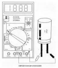
Testing Electrolytic Capacitors with a Digital Multimeter:
Use the capacitance setting to measure; some digital multimeters have the function to measure capacitance, such as UT51, which has ranges of 200μF and 20μF. First, connect the red probe to the current terminal and the black probe to the COM terminal  . Set the function switch to the capacitance range
  . Then connect the red and black probes to the discharged capacitor leads (note the polarity), select the appropriate range, and read the displayed data. The 200μF range is suitable for measuring capacitance between 20μF and 200μF; the 20μF range is suitable for measuring capacitance between 2μF and 20μF.
Using the Buzzer Setting for Preliminary Evaluation of Capacitor Condition
Using the buzzer setting on the digital multimeter, you can quickly check the quality of electrolytic capacitors. The measurement method is shown in the figure above; set the digital multimeter to the buzzer mode  and connect the two probes to the two leads of the capacitor Cx. Then, switch the probes and measure again; the buzzer should sound, indicating that the tested electrolytic capacitor is basically normal. At this point, you can switch to the 20MΩ or 200MΩ high resistance range to measure the capacitor’s leakage resistance, which can help determine its condition. If the buzzer keeps sounding, it indicates that the electrolytic capacitor has previously shorted; if the probes are switched and the buzzer does not sound, and the meter always shows “1”, it indicates that the capacitor is open-circuited or has lost capacity. This method is practical for measuring capacitors greater than 20μF.
Using the Resistance Setting for Preliminary Capacitor Testing
In practice, it has been shown that a digital multimeter can also observe the charging process of a capacitor, which is reflected by the change in voltage on the screen. The following introduces the method of using the digital multimeter’s resistance setting to test capacitors, which is very useful for meters without capacitance settings. This method is suitable for measuring large capacitors from 0.1μF to several thousand microfarads. Set the digital multimeter to an appropriate resistance range, connect the red and black probes to the leads of the capacitor Cx; the displayed value will start from “000” and gradually increase until it shows an overflow symbol “1”. If it continuously shows “000”, it indicates that the capacitor is internally shorted; if it continuously shows overflow, it may indicate that the capacitor is internally open-circuited or that the selected resistance range is inappropriate. When testing electrolytic capacitors, be sure to connect the red probe (positive) to the positive terminal of the capacitor and the black probe to the negative terminal.
Using an Analog Multimeter to Test Electrolytic Capacitors
1. Because electrolytic capacitors have much larger capacitance than general fixed capacitors, the appropriate range should be selected based on different capacitance values. Generally, for capacitors between 1μF and 47μF, the R×1k range can be used for measurement; for capacitors larger than 47μF, the R×100 range can be used. 2. Connect the red probe to the negative terminal and the black probe to the positive terminal. Upon initial contact, the multimeter needle should swing significantly to the right (for the same resistance range, the larger the capacitance, the greater the swing), then gradually return to the left until it stops at a certain position. The resistance value at this point is the forward leakage resistance of the electrolytic capacitor, which is slightly larger than the reverse leakage resistance. Practical experience shows that the leakage resistance of electrolytic capacitors should generally be above several hundred kΩ; otherwise, they will not work properly. If there is no charging phenomenon in both forward and reverse tests, i.e., the needle does not move, it indicates that the capacity has disappeared or that there is an internal open circuit; if the measured resistance is very small or zero, it indicates that the capacitor has significant leakage or has broken down and cannot be used again. 3. For electrolytic capacitors without clear positive and negative markings, the above leakage resistance measurement method can be used to determine polarity. First, measure the leakage resistance arbitrarily and remember its size; then switch the probes and measure again. The measurement with the larger resistance value is the forward connection, indicating that the black probe is connected to the positive terminal and the red probe to the negative terminal. 4. Using the multimeter’s resistance setting, apply forward and reverse charging methods to estimate the capacity of the electrolytic capacitor based on the amplitude of the needle swing.
Set the multimeter to the resistance range, connect the red and black probes to either lead of the color-coded inductor. The needle should swing to the right. Based on the measured resistance value, three specific conditions can be identified: 1. If the resistance value of the color-coded inductor is zero, it indicates an internal short circuit. 2. The size of the direct current resistance value of the color-coded inductor is directly related to the wire gauge and the number of turns used to wind the inductor. As long as a resistance value can be measured, the color-coded inductor can be considered normal.
First, it is important to emphasize that when measuring diodes with a digital multimeter, the measured value is the forward voltage of the diode, while with an analog multimeter, the measured values are the forward and reverse resistances. Diodes can be classified into germanium and silicon types. Germanium diodes have lower forward voltage drops than silicon diodes; 0.1-0.3V indicates a germanium diode, while 0.5-0.8V indicates a silicon diode.
Using an Analog Multimeter to Measure Diode Forward and Reverse Resistance
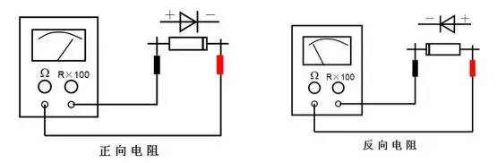 Generally, diodes with low forward resistance are high-frequency diodes, while those with high forward resistance are low-frequency diodes.
Measuring Diode Forward and Reverse Voltage Drops with a Digital Multimeter
1. Insert the red probe into the “V•Ω” jack and the black probe into the “com” jack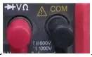 , with the red probe polarity as “+” and the black probe polarity as “-“. 2. Set the function switch to the measurement range, connect the red probe to the positive terminal of the diode and the black probe to the negative terminal of the diode
 . 3. Read the approximate forward voltage drop value from the display; silicon diodes generally have a value of 0.5-0.8V. 4. Connect the red probe to the cathode of the diode
 , and the black probe to the anode of the diode. The multimeter should display a reverse voltage drop, which should show “1” or a very large value.
Assessing Diode Condition
If the forward and reverse resistance values measured with an analog multimeter or the voltage drops measured with a digital multimeter are both very small, it indicates that the diode is internally shorted; if both values are very large or the high value is “1”, it indicates that the diode is internally open-circuited. Measurement notes: When measuring an in-circuit diode, be sure to disconnect the power supply and discharge the relevant capacitors first.
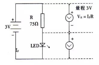
(1) Judging the Polarity of LEDsIn general, the longer lead of an LED is the positive terminal, while the shorter lead is the negative terminal. Another method to determine the polarity of an LED is to observe the shape of the two leads inside the casing under light, as shown in the figure; the longer end is the negative terminal, and the shorter end is the positive terminal.
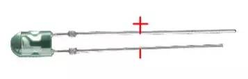
(2) Performance Testing of Ordinary LEDsUse an external power supply for measurement. A 3V steady voltage source or two series-connected dry batteries and a multimeter (either analog or digital) can accurately measure the light and electrical characteristics of an LED. The circuit can be connected as shown in the figure below. If the measured VF is between 1.4 and 3V, and the brightness is normal, it indicates that the LED is functioning properly. If the measured VF is 0 or approximately 3V and it does not light up, it indicates that the LED is damaged. Using the method shown in the figure, the volt-ampere characteristics of the LED can be measured.
(1) Judging the Polarity of Zener DiodesZener diodes are diodes that operate in the reverse breakdown region and have stable voltage characteristics. The measurement of their polarity and performance is similar to that of ordinary diodes.
(2) Testing the Condition of Zener Diodes
If the forward and reverse resistance values measured with an analog multimeter are both very small or infinite, or if the voltage measured with a digital multimeter is very small or very large, it indicates that the Zener diode is either shorted or open-circuited. When the Zener diode is regulating voltage, if the measured stable voltage fluctuates, it indicates that the diode is unstable.
(3) Measuring the Voltage Regulation Value
Using a 0-30V continuously adjustable DC power supply, for Zener diodes below 13V, adjust the output voltage of the power supply to 15V, connect the positive terminal of the power supply in series with a 1.5k limiting resistor to the negative terminal of the Zener diode, and connect the negative terminal of the power supply to the positive terminal of the Zener diode. Then, use a multimeter to measure the voltage across the Zener diode; the measured reading is the voltage regulation value of the Zener diode. If the Zener diode’s voltage regulation value is above 15V, adjust the power supply to above 20V.
PNP (positive-negative-positive) and NPN (negative-positive-negative) 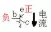 . Different transistor models have different pin configurations. Manufacturers generally provide component parameter tables, and a multimeter can also be used to determine the pin polarity, type, and amplification factor. 1. Determining Pin Polarity and Type of Transistor First, set the multimeter to the diode testing mode
  . Use one probe of the multimeter to contact one of the transistor pins, and use the other probe to test the remaining pins until the following results are obtained: (1) If the black probe is connected to one pin and the red probe measures the other two pins with voltage readings, then this transistor is a PNP transistor, with the black probe connected to the base B. When testing, if the red probe connected to one pin shows a slightly higher voltage, that pin is the emitter E, while the remaining pin with a lower voltage is the collector C. (2) If the red probe is connected to one pin and the black probe measures the other two pins with voltage readings, then this transistor is an NPN transistor, with the red probe connected to the base B. When testing, if the black probe connected to one pin shows a slightly higher voltage, that pin is the emitter E, while the remaining pin with a lower voltage is the collector C. The hFE setting of the digital multimeter can also be used to measure the collector C and emitter E of the transistor. Insert the three pins of the transistor into the e, b, c holes
 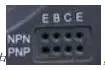 ; if the screen displays a number greater than one hundred, it indicates that the transistor is correctly inserted; if it only shows a few tens, it indicates that the transistor pins are incorrectly inserted. 2. Using the hFE Setting to Measure the Beta Factor Set the range switch to “hFE
  “; at this point, the red and black probes are not in use. Insert the transistor’s e, b, c pins into the e, b, c holes
 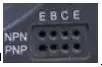 . If the screen displays a number greater than one hundred, that value is the amplification factor β; if it shows “000”, it indicates that the transistor is damaged. 3. Assessing the Condition of the Transistor (1) Check the two PN junctions of the transistor. When testing, use the multimeter to measure the forward and reverse bias of the emitter junction and collector junction; a normal transistor will show good values; otherwise, the transistor is damaged. If the common base cannot be found during the measurement, the transistor is also considered faulty. Taking a PNP transistor as an example, a PNP-type transistor consists of two diodes connected together with negative terminals.
 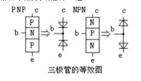 First, use the digital multimeter in diode mode to measure the forward and reverse voltage drops between e and b, and between e and c. When the black probe is connected to b, the red probe should be connected to e and c, showing two small voltage drops. Then, switch the black probe to red and connect it to e and c, which should show two larger voltage drops. If the measured transistor meets the above conditions, it indicates that the transistor is functioning properly. (2) Check the collector-emitter reverse resistance, known as measuring the penetration current. Connect the red probe to the collector c of the PNP transistor and the black probe to the emitter e, and observe the value displayed on the meter; this value should generally be greater than several thousand ohms, the larger the better; the smaller it is, the poorer the stability of the transistor.
4. Mnemonic for Testing Transistors
The identification of transistor types and pins is a basic skill for beginners in electronics. To help readers quickly master the testing methods, I have summarized four mnemonics: “Three Inversion, Find Base; PN Junction, Determine Type; Forward Arrow, Large Deflection; If Uncertain, Use Mouth.” (1) Three Inversion, Find Base: It is known that transistors are semiconductor devices containing two PN junctions. Depending on how the two PN junctions are connected, they can be classified into two types: NPN and PNP. To test a transistor, use the ohm setting on the multimeter and select R×100 or R×1k. For analog multimeters, the red probe connects to the negative terminal of the internal battery, while the black probe connects to the positive terminal. If we do not know whether the tested transistor is NPN or PNP, nor can we distinguish the terminals, the first step is to identify which terminal is the base. We can randomly select two terminals (for example, these two terminals are 1 and 2), use the multimeter to measure their forward and reverse resistance by reversing the probes, and observe the angle of deflection of the needle; then, we can take terminals 1 and 3 and 2 and 3, respectively, and measure their forward and reverse resistances, observing the angle of deflection of the needle. In these three inversion measurements, there will definitely be two measurements that are close: that is, in the inversion measurement, one deflection is large, and the other is small; the remaining measurement will have a very small deflection angle, indicating that the unmeasured terminal is the base. (2) PN Junction, Determine Type: After identifying the base of the transistor, we can determine the conductivity type based on the direction of the PN junction between the base and the other two terminals. Connect the black probe to the base and the red probe to either of the other two terminals; if the meter needle deflects significantly, the tested transistor is an NPN type; if the needle deflection is small, the tested transistor is a PNP type. (3) Forward Arrow, Large Deflection: After identifying the base B, how do we determine which of the other two terminals is the collector C and which is the emitter E? At this point, we can use the penetration current measurement ICEO method to determine the collector C and emitter E. (1) For NPN transistors, according to the principle of the penetration current flow direction in NPN transistors, when measuring the forward and reverse resistances Rce and Rec using the multimeter’s black and red probes, although the needle deflection is small in both measurements, careful observation will reveal that one of them has a slightly larger deflection angle; at this point, the current flow direction must be: black probe → C terminal → B terminal → E terminal → red probe. The current flow direction coincides with the arrow direction in the transistor symbol, so the black probe must be connected to the collector C, and the red probe must be connected to the emitter E. (2) For PNP transistors, the principle is similar to that of NPN; the current flow direction must be: black probe → E terminal → B terminal → C terminal → red probe. The current flow direction also coincides with the arrow direction in the transistor symbol, so the black probe must be connected to the emitter E, and the red probe must be connected to the collector C. (4) If Not Measurable, Use Mouth: If during the measurement of “Forward Arrow, Large Deflection,” the two measurements have small deflections that are difficult to distinguish, then we must “use mouth.” Specifically: during the two measurements of “Forward Arrow, Large Deflection,” hold the junction of the probes and leads with both hands and touch the base B with your mouth (or tongue); you can still use the “Forward Arrow, Large Deflection” method to distinguish between the collector C and emitter E. The human body acts as a DC bias resistance, making the effect more pronounced.
(1) Common Testing Methods Common testing methods for integrated circuits include online measurement, offline measurement, and substitution methods. 1. Offline Measurement Offline measurement occurs when the integrated circuit is not soldered into the circuit; by measuring the DC resistance values between its pins and comparing them with the known normal resistance values of the same model integrated circuit, one can determine whether it is normal. 2. Online Measurement Online measurement uses voltage, resistance, and current measurement methods to check the voltage, resistance, and current values of the integrated circuit pins in the circuit to determine if the integrated circuit is damaged. 3. Substitution Method The substitution method uses a known good integrated circuit of the same model and specifications to replace the tested integrated circuit, allowing one to determine whether the integrated circuit is damaged. 4. Total Current Measurement Method This method checks the total current flowing into the IC power supply to assess its condition. Since most ICs use direct coupling, when an IC is damaged (for example, if a PN junction is shorted or open-circuited), it will cause saturation and cutoff in the subsequent stages, resulting in a change in total current. Therefore, measuring the total current can help determine the condition of the IC. One can also measure the voltage drop across the resistor in the power supply circuit and calculate the total current using Ohm’s law. It is known that when using an integrated circuit, one pin is always soldered to the printed circuit board’s ground line, referred to as the ground pin. Since integrated circuits use direct coupling internally, there is a defined DC resistance between other pins and the ground pin, known as the internal equivalent DC resistance of the pin, abbreviated as R_internal. When acquiring a new integrated circuit, the internal equivalent DC resistance of each pin can be measured with a multimeter. If the internal equivalent resistance R_internal of each pin matches the standard value, it indicates that the integrated circuit is good; otherwise, if it deviates significantly from the standard value, it indicates internal damage to the integrated circuit. One important point to note during measurement is that due to the presence of numerous transistors and diodes within the integrated circuit, measuring a single resistance value is insufficient to assess its condition; both probes should be switched and measured again to obtain both forward and reverse resistance values. Only when both the forward and reverse resistance values of R_internal meet the standard can one determine that the integrated circuit is intact. Based on practical repair experience, it is not necessary to desolder the integrated circuit from the circuit when measuring its internal DC equivalent resistance; simply disconnect the abnormal voltage or resistance pin from the circuit while also disconnecting the ground pin from the circuit board, keeping the other pins intact, and measuring the R_internal forward and reverse resistance values between the testing pin and the ground pin to assess its condition.
How to measure whether a crystal oscillator is oscillating without an oscilloscope. You can use a multimeter to measure the voltage across the two pins of the crystal oscillator to see if it is half of the chip’s operating voltage; for example, if the operating voltage is 5V, check if it is around 2.5V. Additionally, if you touch one pin of the crystal with tweezers, the voltage changes significantly, indicating that it is oscillating.
(1) When measuring resistance with the ohm setting on a multimeter, be sure not to measure with power on, and the measured resistance should not have parallel branches. (2) When measuring high resistance values (e.g., 10M resistors), short the two probes first; the displayed value may be 1M. After each measurement, subtract this value to obtain the actual resistance value (the error will be larger at higher resistance ranges). (3) The internal power supply and connection configuration of analog and digital multimeters:
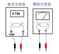
(4) When the size of the voltage (or current) to be measured is unclear, first set to the highest range for a test, then select the appropriate range based on the results. (5) If the multimeter displays a “1” at the highest position and other positions are blank, it indicates that the instrument has been overloaded; a higher range should be selected. (6) When measuring current, if the input current exceeds 2A, the red probe should be connected to the “10A” jack 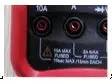 . This jack generally lacks protective devices, so measuring large currents should not exceed 10-15 seconds to prevent the manganin shunt resistor from overheating and altering its resistance value, affecting measurement accuracy. (7) Avoid operational errors, such as measuring voltage with the current range, measuring resistance with voltage or current, or using the capacitance range on charged capacitors, to prevent damage to the instrument. It is especially important to avoid connecting the red probe to the current terminal when measuring high voltage (e.g., 220V), as this may burn out the multimeter.
 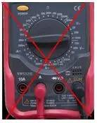 (8) At the beginning of the measurement, the instrument may show jumping numbers; wait for the display value to stabilize before measuring. (9) When measuring resistance, diodes, or checking circuit continuity, connect the red probe to the V•Ω jack; at this time, the red probe is positive, and the black probe is connected to the COM jack, which is negative. This is the opposite of the analog meter’s resistance setting. When testing diodes, transistors, LEDs, electrolytic capacitors, and other polarized components, be sure to pay attention to the probe polarity.
▶ Source: Industrial Control Data Nest
▶ The editor thinks you might also like these  :
:
How many axes do industrial robots actually have? This article clarifies it.
The five major pitfalls of factory automation transformation and the ten essential devices; learn these and you’ll be a pro!
In three years, there will be 1 million industrial robots requiring 200,000 related personnel; can vocational education keep up?
Scan the QR code to add the editor as a friend

 Tell me what you do; after “filing”, I’ll add you to our professional technical group to meet more industry experts!