The full name of CAN is Controller Area Network, which translates to Controller Area Network. It is a half-duplex asynchronous serial communication protocol and physical interface used in embedded systems such as vehicles, power systems, and industrial equipment. CAN is an event-driven communication protocol that employs a non-master-slave structure, allowing all nodes to send and receive data without the need for a master control node. It supports multi-master communication, has priority and conflict resolution mechanisms, and enables efficient data transmission. CAN requires only two signal lines, which are typically twisted pairs, and transmits differential signals. The use of differential signaling provides strong anti-interference capabilities and effectively suppresses external electromagnetic interference.
Operating Principle
The working principle of CAN communication relies on the core components of the CAN interface, including the CAN controller, CAN transceiver, and CAN bus. The role of the CAN transceiver is to convert standard signals into differential signals to enhance anti-interference capability and output reliability. The operating voltage of the CAN bus is typically 5V or 3.3V, but the key to communication lies in the voltage difference between the CAN_High and CAN_Low lines.
After standardization by ISO, the CAN protocol has two standards: ISO11898 and ISO11519-2; among them, the ISO11519-2-1994 standard has been replaced by ISO11898-3-2006, meaning that products compliant with ISO11898-3 are also compliant with ISO11519-2. The ISO11898-2-2016 standard updates and replaces ISO11898-2:2003, ISO11898-5:2007, and ISO11898-6:2013. The definitions of the data link layer in the ISO11898 and ISO11519-2 standards are the same, but the physical layers differ, with the differences between the two standards as follows:
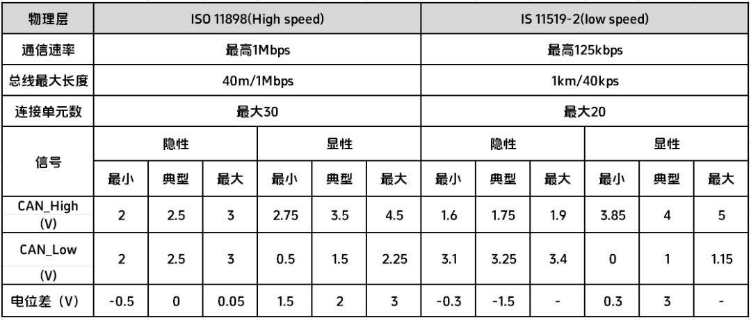
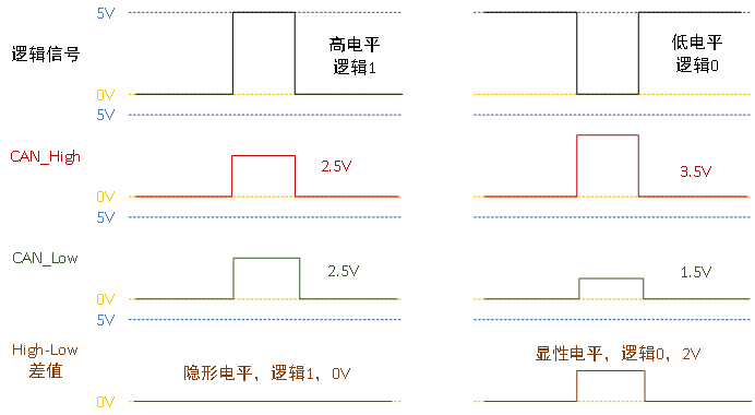
When CAN receives a low-level signal, CAN_High outputs 3.5V, and CAN_Low outputs 1.5V, resulting in a voltage difference of 2V, which indicates a logic 0, also known as a dominant level.
When CAN receives a high-level signal, both CAN_High and CAN_Low output 2.5V, resulting in a voltage difference of 0V, which indicates a logic 1, also known as a recessive level.
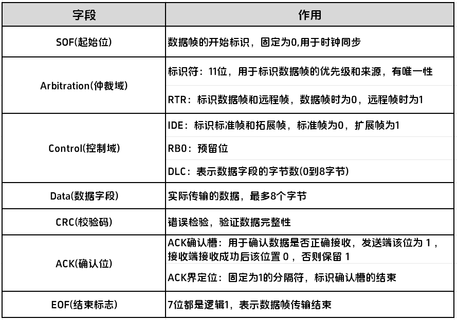
To meet different communication needs, the CAN protocol defines various frame types, including data frames, remote frames, error frames, overload frames, and frame intervals. Data frames are used for transmitting data and contain the actual valid data content; remote frames are used to request data and do not contain data, only sending identifier and length information; error frames indicate errors on the bus, assisting in error handling; overload frames indicate bus overload, helping to manage data flow; and frame intervals are the time intervals between two frames to ensure correct frame transmission and avoid frame conflicts. The most common frame type is the data frame, which is divided into standard data frames and extended data frames.
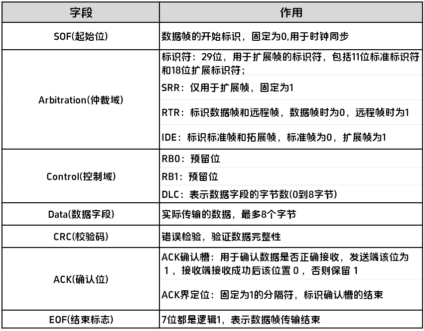
The format and field composition of the standard data frame are as follows:

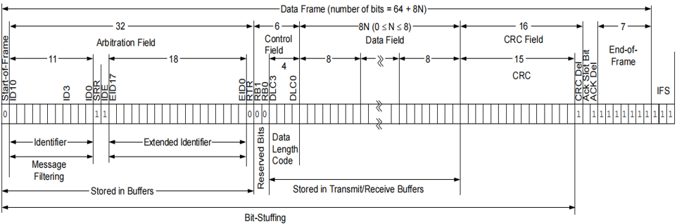
The format and field composition of the extended data frame are as follows:
During normal operation, there may be many devices connected to the CAN bus. If two devices send information simultaneously, a conflict will occur. To avoid bus conflicts, the bus arbitration mechanism must reasonably control and manage the applicants that need to occupy the bus. When multiple applicants request bus access simultaneously, a priority algorithm is used to arbitrate which one should gain access to the bus. Only the device that has obtained bus control can begin transmitting data.
The priority of the message is determined by the arbitration of the ID (identifier). There are two level states on the CAN bus; if both dominant and recessive levels appear simultaneously, the bus state will be set to the dominant level, which is how CAN utilizes this feature for arbitration.
Type Classification
The above introduction pertains to standard CAN. Additionally, there is a type called CAN FD, which stands for Flexible Data Rate. CAN and CAN FD are two different bus standards, both based on CAN technology, but they have significant differences. CAN is a multipoint bus that can connect many devices, while CAN FD is a more advanced multipoint bus that can provide higher transmission rates and greater transmission capacity.
The most significant difference between CAN and CAN FD is the transmission capacity. The maximum transmission capacity of CAN is 8 bytes, while CAN FD can reach a maximum transmission capacity of 64 bytes. This means that CAN FD can provide more data, allowing for larger data packets to be transmitted, thus better meeting application needs.
Another difference is the transmission rate. The maximum transmission rate of CAN is 1 Mbps, while CAN FD can reach a maximum transmission rate of 8 Mbps.
This concludes the core content analysis of the CAN interface. I hope this article can provide practical project practice references for embedded development technology enthusiasts and related university students. If you encounter issues with CAN interface development or debugging in your application scenarios, feel free to contact our technical team for in-depth communication. We will leverage our years of embedded development experience to provide targeted solution recommendations.
