Engineers’ painful lessons: 80% of device bricking incidents stem from Bootloader design flaws!
Introduction
In the late-night production workshop, my colleague Wang stared blankly at the 200 devices that had just failed an upgrade—A single erroneous OTA upgrade directly caused an entire batch of devices to become bricked. This painful experience is not uncommon in the embedded field, and the root cause often lies in critical security vulnerabilities in Bootloader design.
This article will delve into the essence ofBootloader design, based on practical project experience, revealing how to build asecure and reliable STM32 bootloader system that supports OTA. Whether you are a novice just getting started with Bootloader or a seasoned engineer looking to optimize an existing architecture, thedesign principles for security mechanisms andkey code implementations in this article will help you avoid 90% of the pitfalls!
1. Core Points of Bootloader Architecture Design
1. Storage Partition Planning (Foundation to Avoid Bricking)
Dual Zone Design:
// Bootloader code area#define BLOCK_BOOTLOADER_START (BASE_OF_ROM) // 2 sectors 2*16k=32k space#define BLOCK_BOOTLOADER_SPACE (16*1024*4)// APP1 code area#define BLOCK_APP1_START (BLOCK_BOOTLOADER_START + BLOCK_BOOTLOADER_SPACE)#define BLCOK_APP1_SPACE (448*1024)-
Key Strategies:
-
Keep the Bootloader area with a minimal functional set
-
Reserve 10% capacity for future demand changes
-
Implement hardware-independent design through
<span>BOOT_START</span>macros
2. Secure Jump Process (Avoiding Crashes)
Key Operations Before Jump:
// Check if BLOCK_APP1_START is within valid rangeif (BLOCK_APP1_START >= (BASE_OF_ROM + STM32F407ZET6_MAX_SPACE)){ uart_print("Invalid APP start address: 0x%08X\r\n", BLOCK_APP1_START); uart_print("Failed to jump to APP\r\n"); return;}uint32_t _stack_addr = *(volatile uint32_t *) BLOCK_APP1_START; // APP stack top addressuint32_t _reset_handler = *(volatile uint32_t *) (BLOCK_APP1_START + 4); // APP reset interrupt address// Check if stack top address is valid/* For 192KB RAM */if(_stack_addr < 0x20000000 || _stack_addr >= 0x20030000){ uart_print("Invalid stack point : 0x%08X\r\n", _stack_addr); uart_print("Failed to jump to APP\r\n"); return;}// Disable global interrupts__disable_irq();// Clear all pending interruptsfor (int i = 0; i < 8; i++){ NVIC->ICPR[i] = 0xFFFFFFFF; // Clear pending interrupts NVIC->ICER[i] = 0xFFFFFFFF; // Disable interrupts}// 2. Disable SysTick before jumping, reset peripherals used by BootloaderSysTick->CTRL = 0; SysTick->LOAD = 0;SysTick->VAL = 0;// 3. Reset clockHAL_RCC_DeInit();// 4. De-initialize HAL_DeInit(); // De-initialize HAL libraryHAL_UART_MspDeInit(&huart1); // De-initialize UART// HAL_I2C_MspDeInit(&hi2c1); // If there are I2C or other peripherals, they also need to be de-initialized here// Set APP interrupt vector tableSCB->VTOR = BLOCK_APP1_START;// Set main stack pointer__set_MSP(_stack_addr);// Memory barrier__DSB();__ISB();// Jump to APP, starting address is MSP, address +4 is the reset interrupt reset program addressAPP_MAIN_FUNC App_Main = (APP_MAIN_FUNC) _reset_handler;App_Main();Address Verification Mechanism:
// Check if BLOCK_APP1_START is within valid rangeif (BLOCK_APP1_START >= (BASE_OF_ROM + STM32F407ZET6_MAX_SPACE)){ uart_print("Invalid APP start address: 0x%08X\r\n", BLOCK_APP1_START); uart_print("Failed to jump to APP\r\n"); return;}// Check if stack top address is valid/* For 192KB RAM */if(_stack_addr < 0x20000000 || _stack_addr >= 0x20030000){ uart_print("Invalid stack point : 0x%08X\r\n", _stack_addr); uart_print("Failed to jump to APP\r\n"); return;}2. Key Implementation of Firmware Transfer (Ymodem Practical)
1. Protocol Selection: Why Ymodem?
| Feature | Xmodem | Ymodem | Industrial Choice |
|---|---|---|---|
| Packet Size | 128B | 128B/1024B | ✅ |
| Filename Support | ❌ | ✅ | ✅ |
| File Size Support | ❌ | ✅ | ✅ |
| Transmission Efficiency | Low | High | ✅ |
2. Core Algorithm for CRC Check
/** * @brief Update CRC16 for input byte * @param crc_in input value * @param input byte * @retval None */ uint16_t UpdateCRC16(uint16_t crc_in, uint8_t byte) { uint32_t crc = crc_in; uint32_t in = byte | 0x100; do { crc <<= 1; in <<= 1; if (in & 0x100) ++crc; if (crc & 0x10000) crc ^= 0x1021; }while (!(in & 0x10000)); return crc & 0xffffu; } /** * @brief Cal CRC16 for YModem Packet * @param data * @param length * @retval None */ uint16_t Cal_CRC16(const uint8_t *p_data, uint32_t size) { uint32_t crc = 0; const uint8_t *dataEnd = p_data + size; while (p_data < dataEnd) crc = UpdateCRC16(crc, *p_data++); crc = UpdateCRC16(crc, 0); crc = UpdateCRC16(crc, 0); return crc & 0xffffu; }3. Pitfall Guide for Flash Operations
Golden Rules for Flash Writing:
int32_t Stm32_flash_Write(uint32_t addr,uint8_t *buf,uint32_t size){ uint32_t end_addr = addr + size; uint32_t data = 0; if (end_addr > FLASH_END_ADDR) { return -10; } if (size < 1) { return -10; } // If length is not a multiple of 4 bytes, pad to the new 4 bytes (ymodem 128,1024 are all 4-byte aligned, generally won't occur) // Use temporary buffer uint32_t padded_size = (size + 3) & ~0x03; // Calculate aligned size uint8_t padded_buf[padded_size]; memset(padded_buf, 0xFF, padded_size); // Fill with 0xFF (Flash erase state) memcpy(padded_buf, buf, size); // Copy original data // Unlock flash HAL_FLASH_Unlock(); __HAL_FLASH_CLEAR_FLAG(FLASH_FLAG_EOP | FLASH_FLAG_OPERR | FLASH_FLAG_WRPERR | FLASH_FLAG_PGAERR | FLASH_FLAG_PGPERR | FLASH_FLAG_PGSERR); for (uint32_t i = 0; i < (padded_size/4); i++) { // Store in little-endian format data = padded_buf[i*4 + 0]; data |= padded_buf[i*4 + 1] << 8; data |= padded_buf[i*4 + 2] << 16; data |= padded_buf[i*4 + 3] << 24; if (HAL_FLASH_Program(FLASH_TYPEPROGRAM_WORD, addr,data) != HAL_OK) { return -1; } // Verify write if (*(uint32_t*)addr != data) { HAL_FLASH_Lock(); return -2; // Verification failed } addr += 4; } HAL_FLASH_Lock(); return (int32_t)size;}Three Common Mistakes and Solutions:
-
Unaligned Address: Force 4-byte alignment processing
-
Write Protection Failure: Lock/Unlock before and after operations
-
Missing Verification: Compare byte by byte after writing
4. Security Mechanism Design (Lifeline Clause)
1. OTA Flag Mechanism
uint32_t flag = *(uint32_t*)OTA_FLAG_ADDR;if(flag == 0xAA559966) // Magic number verification{ Bootloader_JumpToApp();} else { SerialDownload();}2. Triple Insurance Against Bricking
-
Pre-check Mechanism: First verify file size, then erase Flash
-
Dual Zone Isolation: Hardware write protection for Bootloader area
-
Rollback Design: Keep a backup area for the previous firmware version (to be added later)
5. Industrial-Level Boot Process Analysis
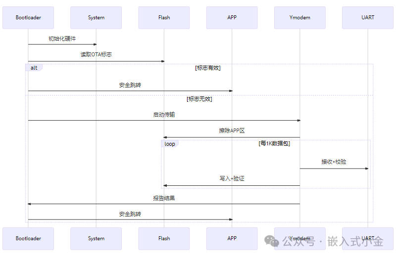
Conclusion
Areliable Bootloader must be as precise as a Swiss watch—every gear’s engagement is crucial to the system’s life and death. The three core modules revealed in this article,secure jump mechanisms, firmware transfer protocol selection, and Flash operation specifications, are the foundation for building an industrial-grade boot system.
Discussion: What “thrilling” failures have you encountered in Bootloader development? Or do you have better implementation solutions for the security mechanisms mentioned in the article?Feel free to share your practical experiences in the comments!
Did you find this article helpful? Please like 👍, share, and bookmark 📁 to support us!
Original Statement: This article is originally published by 【Embedded Xiao Jin】. Feel free to share. For reprints, please contact for authorization.
Get Resources: Follow our public account, reply with“boot code”, to get the complete project code of this article!
Author: Xiao Jin