
1. Background of Industrial Robot Development
In 1920, Czech playwright Karel Čapek first used the term ROBOT in his science fiction play “Rossum’s Universal Robots,” which subsequently became synonymous with robots.
In March 1938, The Meccano Magazine reported on a model of a handling robot, marking one of the earliest reports of a robot model aimed at industrial applications. It was designed by Griffith P. Taylor in 1935 and could achieve five-axis movement through an electric motor. By 1954, G.C. Devol from the USA designed the first electronically programmable industrial robot. In 1960, AMF Corporation produced the Versatran robot, a cylindrical coordinate robot capable of point and trajectory control, which was the first robot used in industrial production.
In 1974, Cincinnati Milacron successfully developed a multi-joint robot. By 1979, Unimation launched the PUMA robot, a multi-joint, all-electric, multi-CPU secondary control robot that utilized a dedicated VAL language and could be equipped with visual, tactile, and force sensors, making it the most advanced industrial robot of its time. Modern industrial robots are largely based on this structure. Robots from this period were classified as “Teach-in/Playback” robots, which only had memory and storage capabilities, repeating tasks according to corresponding programs, with little perception or feedback control of their surrounding environment.
Entering the 1980s, with the development of sensing technologies, including visual sensors, non-visual sensors, and information processing technologies, the second generation of robots—sensing robots—emerged. They can obtain some relevant information about their working environment and objects, perform real-time processing, and guide the robot to carry out tasks. Second-generation robots have been widely used in industrial production.
Currently, countries are researching “smart robots,” which not only have superior environmental perception capabilities compared to second-generation robots but also possess logical thinking, judgment, and decision-making abilities, allowing them to work autonomously based on task requirements and environmental information.
2. Application Scenarios of Industrial Robots
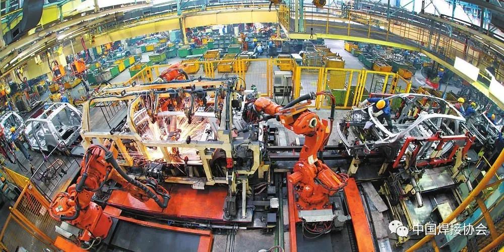
Since the creation of the first industrial robot in the early 1960s, robots have demonstrated significant vitality. In just over 50 years, robot technology has rapidly developed, with industrial robots being most widely used in the automotive and automotive parts manufacturing industries, and continuously expanding into other fields such as mechanical processing, electronics and electrical engineering, rubber and plastics, food industry, and wood and furniture manufacturing. In industrial production, welding robots, grinding and polishing robots, laser processing robots, painting robots, handling robots, and vacuum robots have been widely adopted. Below is an introduction to the application scenarios and technical characteristics of industrial robots.
3. Current Status of Industrial Robots
With the rise of industrial robots, “machine substitution” is becoming a trend. Foxconn previously announced that it would purchase one million robots within three years, with plans to establish the “world’s largest intelligent robot production base” in Jincheng, Shanxi, by 2016.
The six major manufacturing industries of automotive, electronics, food, chemicals, rubber and plastics, and metal products are considered the main areas currently applying industrial robots. Institutions predict that there will be an annual demand of 1 million to 2 million units, accounting for about 70% of the demand in the Chinese industrial robot market.
As of September this year, there are nearly 420 robot companies in China. Additionally, more than 30 robot industrial parks are currently under construction across the country.
The reason industrial robots have emerged strongly in the Chinese market is primarily due to cost; robots typically cost only a quarter of labor costs. Furthermore, robots can bring significant added value in terms of quality, efficiency, and management. Therefore, under the combined effect of rapidly improving robot technology, significantly declining prices, labor shortages, and rising labor costs, China’s industrial robot industry is in a period of explosive growth.
4. Key Technologies of Industrial Robots
1. Basic System Composition of Robots
Industrial robots consist of three major parts and six subsystems. The three major parts are the mechanical part, sensing part, and control part. The six subsystems can be divided into mechanical structure system, drive system, perception system, robot environment interaction system, human-machine interaction system, and control system.
1) The mechanical structure system of industrial robots consists of three main parts: the base, arm, and end effector. Each major component has several degrees of freedom in its mechanical system. If the base is equipped with a walking mechanism, it forms a mobile robot; if the base lacks walking and bending mechanisms, it forms a single robotic arm. The arm typically consists of an upper arm, lower arm, and wrist. The end effector is an important component directly mounted on the wrist, which can be a two-finger or multi-finger gripper, or tools such as paint sprayers or welding equipment.
2) The drive system is necessary to make the robot operate, requiring the installation of transmission devices at each joint, i.e., each degree of freedom. The drive system can be hydraulic, pneumatic, electric, or a combination of these basic types into a composite drive system. This drive system can be direct drive or indirect drive through mechanical transmission mechanisms such as synchronous belts, chains, gear systems, or harmonic gear systems.
3) The perception system consists of internal sensor modules and external sensor modules to obtain meaningful information about internal and external environmental states. The use of smart sensors enhances the robot’s mobility, adaptability, and intelligence. While the human sensory system is highly adept at perceiving external world information, sensors can be more effective for certain specific information.
4) The robot environment interaction system is a system for modern industrial robots to interact and coordinate with external devices. Industrial robots are integrated with external devices into a functional unit, such as processing units, welding units, assembly units, etc. It can also be multiple robots, machine tools, or storage devices for parts combined into a functional unit to perform complex tasks.
5) The human-machine interaction system is the device through which the operator controls and communicates with the robot. Examples include standard terminals, command consoles, information display boards, and danger signal alarms. This system can be categorized into two main types: command input devices and information display devices.
6) The robot control system is the brain of the robot, which is the main factor determining the robot’s functions and performance.
The control system’s task is to command the robot’s actuators to complete specified movements and functions based on the robot’s operational instruction program and feedback signals from sensors. If the industrial robot lacks information feedback features, it is an open-loop control system; if it possesses information feedback features, it is a closed-loop control system. Based on control principles, control systems can be divided into program control systems, adaptive control systems, and artificial intelligence control systems. Based on the form of control operations, control systems can be divided into point control and trajectory control. Point control only accurately positions the actuator from one point to another, suitable for machine tool loading and unloading, spot welding, and general handling tasks; continuous trajectory control can guide the actuator to move along a specified trajectory, suitable for continuous welding and painting operations.
The control system’s task is to command the robot’s actuators to complete specified movements and functions based on the robot’s operational instruction program and feedback signals from sensors. If the industrial robot lacks information feedback features, it is an open-loop control system; if it possesses information feedback features, it is a closed-loop control system. Based on control principles, control systems can be divided into program control systems, adaptive control systems, and artificial intelligence control systems. Based on the form of control operations, control systems can be divided into point control and trajectory control. A complete industrial robot includes the robot body, system software, control cabinet, peripheral mechanical devices, CCD vision, grippers, peripheral device PLC control cabinet, and teaching device/teaching box.
Below we focus on the drive system and perception system of robots.
2. Robot Drive System
The drive system of industrial robots can be categorized into three main types based on the power source: hydraulic, pneumatic, and electric. These three basic types can also be combined to form composite drive systems. Each of these three basic drive systems has its own characteristics.
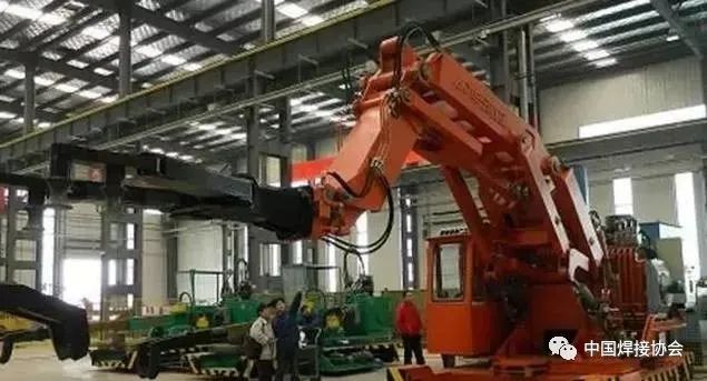
Hydraulic drive systems: Due to the maturity of hydraulic technology, they have advantages such as high power, a large ratio of force (or torque) to inertia, fast response, and ease of direct drive implementation. They are suitable for robots that work in environments with large load capacities and inertia, as well as in welding applications. However, hydraulic systems require energy conversion (from electrical energy to hydraulic energy), and speed control is mostly achieved through throttling, which is less efficient than electric drive systems. Leakage of hydraulic fluids can cause environmental pollution, and working noise is also relatively high. Due to these shortcomings, electric systems have often replaced hydraulic systems in robots with loads of 100 kg or less in recent years.
The fully hydraulic heavy-duty robot developed by Qingdao Huadong Engineering Machinery Co., Ltd. is shown in the figure. Its large-span load capacity can reach 2000 kg, and the robot’s working radius can reach nearly 6 m, applied in the casting and forging industry.
 Fully Hydraulic Heavy-Duty Robot
Pneumatic drive systems have advantages such as fast speed, simple system structure, easy maintenance, and low cost. However, due to the low working pressure of pneumatic devices, precise positioning is difficult, and they are generally used only for the drive of end effectors in industrial robots. Pneumatic grippers, rotary cylinders, and pneumatic suction cups can be used for handling and assembly of medium and small loads. Pneumatic suction cups and pneumatic robot grippers are shown in the figure.
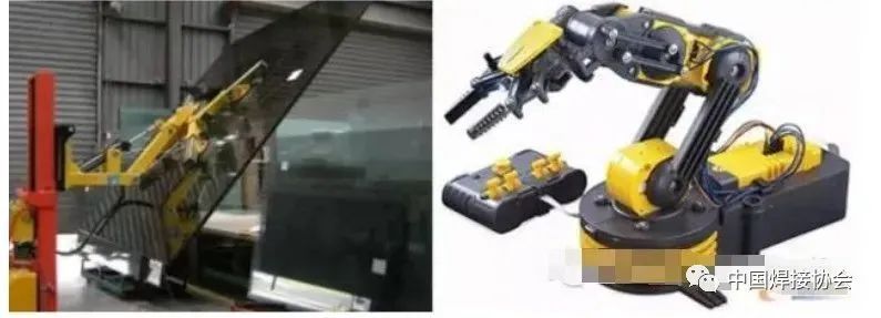 Pneumatic Suction Cups and Pneumatic Robot Grippers
Electric drive systems are a mainstream driving method for modern industrial robots, divided into four main categories of motors: DC servo motors, AC servo motors, stepper motors, and linear motors. DC servo motors and AC servo motors utilize closed-loop control, generally used for high-precision and high-speed robot drives; stepper motors are used in cases where precision and speed requirements are not high, employing open-loop control; linear motors and their drive control systems have become increasingly mature, exhibiting superior performance compared to traditional transmission devices, such as suitability for very high-speed and very low-speed applications, high acceleration, high precision, minimal backlash, low wear, simple structure, and no need for reducers and gear screw couplings. Due to the high demand for linear drives in parallel robots, linear motors have been widely applied in this field.
3. Robot Perception System
The robot perception system converts various internal state information and environmental information from signals into data and information that the robot itself or robots can understand and apply. In addition to needing to perceive mechanical quantities related to its working status, such as displacement, speed, acceleration, force, and torque, visual perception technology is an important aspect of industrial robot perception.
The visual servo system uses visual information as feedback signals to control and adjust the robot’s position and posture. This application is mainly reflected in the semiconductor and electronics industries. The machine vision system has also been widely used in quality inspection, workpiece recognition, food sorting, and packaging.
Typically, robot visual servo control is based on position-based visual servoing or image-based visual servoing, also known as three-dimensional visual servoing and two-dimensional visual servoing, respectively. Each of these methods has its advantages and applicability, but they also have some drawbacks, leading to the proposal of a 2.5-dimensional visual servoing method.
Position-based visual servo systems utilize camera parameters to establish a mapping relationship between image information and the position/posture information of the robot’s end effector, achieving closed-loop control of the end effector’s position. The position and posture errors of the end effector are estimated based on the position information extracted from the real-time captured images and the geometric model of the positioning target. Then, based on the position and posture errors, new pose parameters for each joint are obtained. Position-based visual servoing requires that the end effector is always observable in the visual scene and that its three-dimensional position and posture information can be calculated. Eliminating interference and noise in images is crucial for ensuring the accuracy of position and posture error calculations.
Two-dimensional visual servoing compares features between images captured by cameras and given images (not three-dimensional geometric information) to derive error signals. Then, corrections are made through joint controllers and visual controllers based on the robot’s current operational status to complete servo control. Compared to three-dimensional visual servoing, two-dimensional visual servoing is more robust to calibration errors of cameras and robots, but during the design of the visual servo controller, it inevitably encounters issues such as singularities in the image Jacobian matrix and local minima.
To address the limitations of three-dimensional and two-dimensional visual servoing methods, F. Chaumette and others proposed a 2.5-dimensional visual servoing method. This method decouples the closed-loop control of camera translational motion and rotation based on image feature points, reconstructing the orientation and imaging depth ratio of objects in three-dimensional space. The translational part is represented by the coordinates of feature points on the image plane. This method successfully combines image signals and pose signals extracted from images, integrating the error signals they produce for feedback, greatly alleviating issues of robustness, singularities, and local minima. However, some problems still need resolution, such as ensuring that the reference object remains within the camera’s field of view during the servo process and the non-uniqueness of the solutions when decomposing the homography matrix.
When establishing the visual controller model, it is necessary to find a suitable model to describe the mapping relationship between the robot’s end effector and the camera. The image Jacobian matrix method is a widely used approach in the field of robot visual servo research. Since the Jacobian matrix of the image is time-varying, it needs to be calculated or estimated online.
4. Key Basic Components of Robots
Robots consist of four major components, with the body cost accounting for 22%, servo system 24%, reducer 36%, and controller 12%. Key basic components of robots refer to units that constitute the robot’s drive system, control system, and human-machine interaction system, significantly influencing robot performance and possessing generality and modularity. The key basic components of robots can be divided into the following three parts: high-precision robot reducers, high-performance AC/DC servo motors and drivers, and high-performance robot controllers.
1) Reducers
The reducer is a key component of robots, and currently, two main types of reducers are primarily used: harmonic gear reducers and RV reducers.

The harmonic drive method was invented by American inventor C. Walt Musser in the mid-1950s. The harmonic gear reducer consists mainly of three basic components: a wave generator, a flexible gear, and a rigid gear, relying on the wave generator to create controllable elastic deformation in the flexible gear, engaging with the rigid gear to transmit motion and power. The single-stage transmission ratio can reach 70 to 1000, and the deformation of the flexible gear allows for backlash-free engagement during reversal. Compared to general reducers, the volume of harmonic gear reducers can be reduced by two-thirds, and weight can be reduced by half while maintaining the same output torque. The flexible gear endures significant alternating loads, thus requiring high fatigue strength, processing, and heat treatment standards, making the manufacturing process complex. The performance of the flexible gear is key to high-quality harmonic gear reducers.
In 1926, German Lorenz Baraen proposed the principle of cycloidal pinwheel planetary gear transmission, and in the 1980s, Teijin Co., Ltd. of Japan was the first to develop the RV reducer. The RV reducer consists of a pre-stage planetary gear reducer and a post-stage cycloidal pinwheel reducer. Compared to harmonic gear reducers, RV reducers offer better rotational accuracy and precision retention.
Chen Shixian invented the active tooth transmission technology. The fourth generation of active tooth transmission—the fully rolling active tooth transmission (oscillatory roller transmission, ORT)—has been successfully applied to various industrial products. The compound rolling active tooth transmission (CORT) proposed based on ORT not only has advantages similar to RV transmission but also overcomes the drawbacks of RV transmission, such as high bearing load and low lifespan, further enhancing service life and load capacity. The structure of CORT leads to smaller backlash under the same precision indicators, higher motion precision and rigidity, alleviating the defect of RV transmission requiring high manufacturing precision, potentially reducing processing requirements and manufacturing costs. CORT is independently developed in China and possesses independent intellectual property rights. Both Anshan Wear-Resistant Alloy Research Institute and Zhejiang Hengfeng Tai Reducer Manufacturing Co., Ltd. have successfully developed CORT reducers for robots.
ORT Reducer CORT Reducer
Currently, in the field of high-precision robot reducers, 75% of the market share is monopolized by two Japanese reducer companies: Nabtesco, which provides RV cycloidal pinwheel reducers, and Harmonic Drive, which offers high-performance harmonic reducers. Mainstream international robot manufacturers, including ABB, FANUC, KUKA, and MOTOMAN, source their reducers from these two companies. Unlike the general models selected by domestic robot companies, mainstream international robot manufacturers have signed strategic cooperation agreements with these two companies, with most of the products provided being specialized models modified based on general models according to each manufacturer’s specific requirements. Domestic research on high-precision cycloidal pinwheel reducers has started relatively late, with only a few educational institutions having conducted related research. Currently, there are no mature products applied in industrial robots. In recent years, some domestic manufacturers and institutions have begun to focus on the localization and industrialization of high-precision cycloidal pinwheel reducers, such as Zhejiang Hengfeng Tai, Chongqing University’s National Key Laboratory of Mechanical Transmission, Tianjin Reducer Factory, Qin Chuan Machine Tool Factory, and Dalian Railway Institute.
In terms of harmonic reducers, domestic alternatives have emerged, such as Beijing Zhongji Kemei and Beijing Harmonic Drive Institute; however, their corresponding products still exhibit significant gaps in input speed, torsional rigidity, transmission precision, and efficiency compared to Japanese products, with mature applications in industrial robots just beginning.
Comparative performance of mainstream high-precision harmonic reducers in domestic and international industrial robots is shown in the following table.
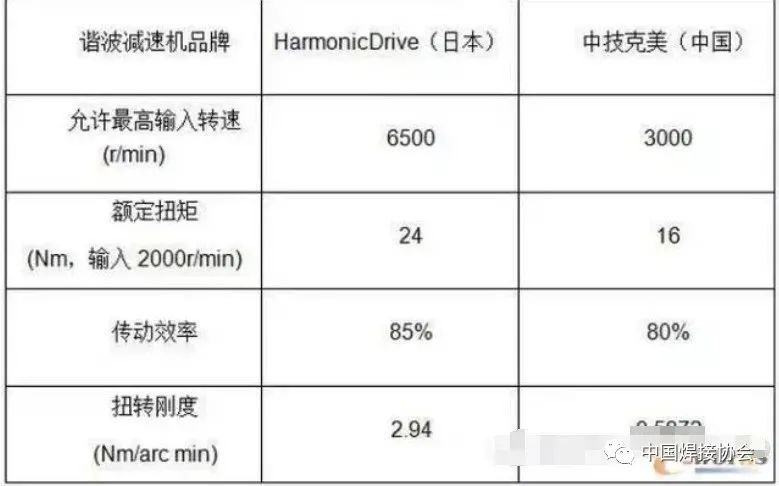
Table 1 Performance Comparison of Mainstream High-Precision Harmonic Reducers
Note: The comparative data in the table is from similar models:
HD: CSF-17-100
Zhongji Kemei: XB1-40-100
Transmission efficiency test conditions: input speed 1000r/min, temperature 40°
Torsional rigidity test conditions: within 20% rated torque
Comparative performance of mainstream high-precision cycloidal pinwheel reducers in domestic and international industrial robots is shown in the following table.
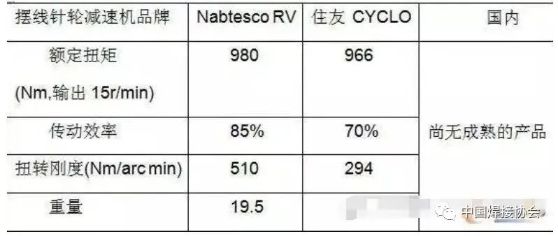
Table 2 Performance Comparison of Mainstream High-Precision RV Cycloidal Pinwheel Reducers
Note: The comparative data in the table is from similar models:
RV: 100C
CYCLO: F2CF-C35
Transmission efficiency test conditions: output speed 15r/min, rated torque
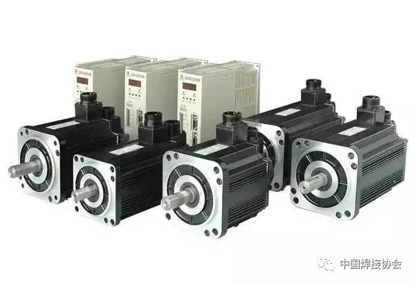
2) Servo Motors
In terms of servo motors and drives, the driving components of European robots are mainly provided by companies such as Lenze, Lust, and Bosch Rexroth, which offer good overload capability, dynamic response, and open drive interfaces, but at a high cost. Key components of Japanese brand industrial robots are mainly provided by Yaskawa, Panasonic, and Mitsubishi, which are relatively lower in price but exhibit poorer dynamic response and openness, with most only supporting analog and pulse control methods. In recent years, domestic research and industrialization of high-power AC permanent magnet synchronous motors and drives have been initiated by institutions such as Harbin Institute of Technology, Beijing Heli, and Guangzhou CNC, and they have achieved some production capabilities; however, their dynamic performance, openness, and reliability still need to be validated through more practical robot projects.
3) Controllers
In terms of robot controllers, mainstream foreign robot manufacturers’ controllers are developed independently based on general multi-axis motion control platforms. The general multi-axis controllers are mainly categorized into motion control cards based on embedded processors (DSP, POWER PC) and PLC systems based on industrial computers with real-time systems, represented respectively by Delta Tau’s PMAC card and Beckhoff’s TwinCAT system. In terms of motion control cards, the domestic company Sogou has developed corresponding mature products, but their application in robots is still relatively limited.
5. Robot Operating Systems
The Robot Operating System (ROS) is a standardized construction platform designed for robots, enabling every robot designer to use the same operating system for robot software development. ROS will promote the robot industry toward hardware and software independence. The independent development model of hardware and software has significantly facilitated the development and rapid advancement of PC, laptops, and smartphone technologies.
The difficulty of developing ROS is greater than that of computer operating systems, as computers only need to handle clearly defined mathematical operations, while robots must deal with more complex practical motion operations.
ROS provides standard operating system services, including hardware abstraction, low-level device control, common function implementations, inter-process messaging, and data packet management.
ROS is divided into two layers: the lower layer is the operating system layer, and the upper layer consists of various software packages contributed by users to implement different functions for robots.
The existing robot operating system architectures are mainly based on the open-source Linux Ubuntu operating system. Additionally, various ROS systems have been developed by institutions such as Stanford University, MIT, and Munich University. In 2007, the Microsoft robotics development team also launched a “Windows Robot Version.”
6. Robot Motion Planning
To improve work efficiency and enable robots to complete specific tasks in the shortest possible time, reasonable motion planning is essential. Offline motion planning is divided into path planning and trajectory planning.
The goal of path planning is to maximize the distance between the path and obstacles while minimizing the path length; the purpose of trajectory planning is primarily to minimize the robot’s running time during joint space movement or to minimize energy consumption. Trajectory planning adds time sequence information based on path planning to plan the speed and acceleration of the robot during task execution, ensuring smoothness and controllability of speed.
Teach-in playback is one method to achieve path planning, where the operator teaches through the operational space and records the teaching results to reproduce them during work. On-site teaching directly corresponds to the actions that the robot needs to perform, with intuitive and clear paths. The downside is that it requires experienced operators and consumes a lot of time, and the paths may not be optimized. To address these issues, a virtual model of the robot can be established to complete path planning for operational tasks through visualized virtual operations.
Path planning can be performed in joint space. Gasparetto used quintic B-splines as interpolation functions for joint trajectories and optimized the integral of the square of acceleration concerning motion time as the objective function to ensure that the movements of each joint are sufficiently smooth. Liu Songguo used quintic B-splines for interpolation calculations of the robot’s joint trajectories, allowing for arbitrary configuration of the speed and acceleration endpoint values of each joint based on smoothness requirements. Additionally, trajectory planning in joint space can avoid singularity issues in operational space. Huo et al. designed a joint trajectory optimization algorithm to avoid singularities in joint space, utilizing the redundancy of a 6-degree-of-freedom arc welding robot during task execution and treating robot singularity and joint constraints as constraints, using the TWA method for optimization calculations.
Joint space path planning has the following advantages compared to operational space path planning:
Avoids the singularity issues of robots in operational space;
Since robot motion is controlled by the movement of joint motors, in joint space, it avoids a large number of forward and inverse kinematic calculations;
Joint space trajectories are easier to optimize for control.
5. Classification of Industrial Robots
Industrial robots can be classified into the following types based on different methods:
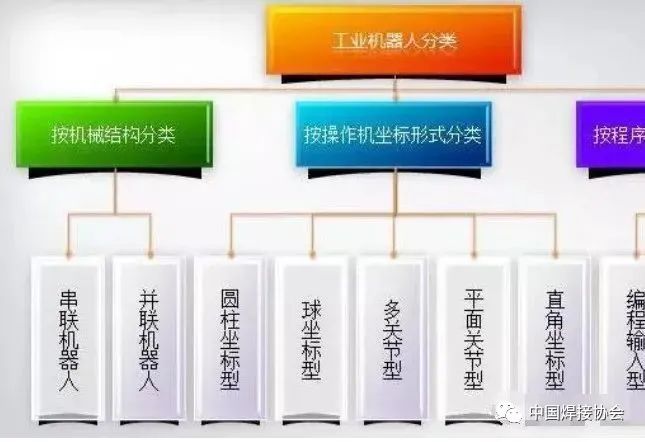
Classification of Industrial Robots
1. From the perspective of mechanical structure, they are divided into serial robots and parallel robots.
1) The characteristic of serial robots is that the motion of one axis changes the origin of another axis. In terms of position solving, the forward solution of serial robots is easy, but the inverse solution is very difficult;
2) Parallel robots use parallel mechanisms, where the motion of one axis does not change the origin of another axis. Parallel robots have advantages such as high rigidity, stable structure, large load capacity, high micro-motion precision, and low motion load. Their forward solution is difficult, but the inverse solution is very easy. Serial robots and parallel robots are shown in the figure.
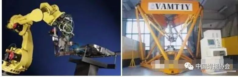
Serial Robots, Parallel Robots
2. Industrial robots can be classified into the following categories based on the form of operational machine coordinates: (The coordinate form refers to the reference coordinate system taken by the arm of the operational machine during movement.)
1) Cartesian coordinate industrial robots
The motion part consists of three mutually perpendicular linear movements (i.e., PPP), and its working space is rectangular. The movement distances along each axis can be directly read on each coordinate axis, making it intuitive for programming calculations of position and posture, with high positioning accuracy, uncoupled control, and simple structure. However, the space occupied by the body is large, the range of motion is small, and flexibility is poor, making it difficult to coordinate with other industrial robots.
2) Cylindrical coordinate industrial robots
The motion form consists of a rotational movement and two linear movements, and its working space is cylindrical. Compared to Cartesian coordinate industrial robots, it occupies less space under the same working space conditions while having a larger range of motion. Its positioning accuracy is second only to Cartesian coordinate robots, but it is also difficult to coordinate with other industrial robots.
3) Spherical coordinate industrial robots
Spherical coordinate industrial robots, also known as polar coordinate industrial robots, consist of two rotational movements and one linear movement (i.e., RRP, one rotation, one pitch, and one stretch). Their working space is a sphere, allowing them to perform pitch movements and grasp coordinate workpieces on the ground or at lower positions, with high positioning accuracy, where positioning errors are proportional to arm length.
4) Multi-joint industrial robots
Also known as revolute coordinate industrial robots, the arms of these industrial robots are similar to human upper limbs. Their first three joints are revolute pairs (i.e., RRR), and the industrial robot is generally composed of a column and large and small arms, forming shoulder joints between the column and large arm and elbow joints between the large and small arms, allowing the large arm to perform rotational movements and pitch oscillation, while the small arm performs pitch oscillation. They have the most compact structure, high flexibility, and occupy the smallest area, enabling coordination with other industrial robots, but their positioning accuracy is relatively low, and they have balance issues and control coupling, making them increasingly widely used in applications.
5) Planar joint industrial robots
They use one mobile joint and two revolute joints (i.e., PRR), where the mobile joint achieves up-and-down movement while the two revolute joints control front-back and left-right movements. This form of industrial robot is also known as the SCARA (Selective Compliance Assembly Robot Arm) assembly robot. It has compliance in the horizontal direction and significant rigidity in the vertical direction. Its simple structure and flexible movements make it widely used in assembly tasks, particularly suitable for the insertion and assembly of small parts, such as in the electronics industry.
3. Industrial robots can be distinguished by their programming input methods into programmed input types and teach input types:
1) Programmed input types transmit pre-written operational program files from a computer to the robot control cabinet via RS232 serial ports or Ethernet communication.
2) Teach input types have two teaching methods: teaching box teaching and direct manipulation by the operator to teach the executing mechanism.
Teaching box teaching involves the operator using a manual controller (teaching box) to send command signals to the drive system, making the executing mechanism perform the required sequence of actions and motion trajectories. Industrial robots using teaching boxes are quite common, and most industrial robots are equipped with teaching box functions. However, for complex trajectory situations, teaching box teaching may not yield ideal results, such as in painting robots used for complex surface spraying operations.
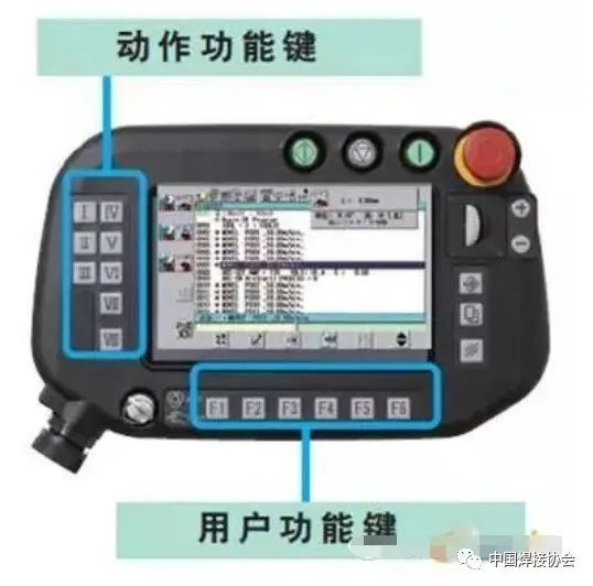
Robot Teaching Box
Direct manipulation by the operator to teach involves performing the required sequence of actions and motion trajectories. Simultaneously during the teaching process, the information of the working program is automatically stored in the program memory. When the robot operates automatically, the control system retrieves the corresponding information from the program memory, sending command signals to the driving mechanism to reproduce the various actions taught.
6. Performance Evaluation Indicators of Industrial Robots
The basic parameters and performance indicators that represent the characteristics of robots mainly include working space, degrees of freedom, effective load, motion accuracy, motion characteristics, and dynamic characteristics.
1. Performance Evaluation Indicators of Industrial Robots
Working space (Work space) refers to the set of positions in space that specific parts of the robot arm can reach under certain conditions. The characteristics and size of the working space reflect the robot’s working capacity. When understanding a robot’s working space, the following points should be noted:
1) The working space indicated in industrial robot manuals typically refers to the range that the mechanical interface coordinate system’s origin on the wrist can reach in space, i.e., the range that the center point of the wrist flange can reach in space, rather than the range that the end effector’s endpoint can reach. Therefore, when designing and selecting, it is essential to consider the actual working space the robot can reach after installing the end effector.
2) The working space provided in the robot manual is often smaller than the maximum space in a kinematic sense. This is because, in the reachable space, the effective load, maximum speed, and maximum acceleration differ depending on the arm’s posture, with the maximum allowable limits typically smaller at the arm’s maximum position than at other positions. Additionally, singular configurations, where the robot’s degrees of freedom degenerate, may exist at the boundaries of the maximum reachable space, and a significant range around singular configurations will also exhibit degeneracy, rendering that portion of the working space unusable during robot operation.
3) In addition to the edges of the working space, practical industrial robots may also have areas within the working space that the arm’s end cannot reach due to mechanical structure limitations, referred to as cavities or voids. A cavity is a completely enclosed space within the working space that the arm’s end cannot reach, while a void refers to a space around the rotation axis that the arm’s end cannot reach along its entire length.
2. Degrees of Freedom
Degrees of freedom refer to the number of variables required for the robot’s operational machine to move in space, representing the flexibility of robot actions, generally indicated by the number of independent movements along axes and around axes.
A free object in space has six degrees of freedom (three rotational and three translational). Industrial robots are often open-chain linkages, with each joint movement pair having one degree of freedom, so the number of degrees of freedom for a robot typically equals its number of joints. The greater the number of degrees of freedom, the stronger the robot’s functionality. Currently, industrial robots typically have 4 to 6 degrees of freedom. When the number of joints (degrees of freedom) exceeds the requirements for orienting and positioning the end effector, redundancy occurs. The emergence of redundancy increases the robot’s operational flexibility but also complicates control.
In terms of motion modes, industrial robots can be divided into linear motion (denoted as P) and rotational motion (denoted as R). The application of abbreviated symbols P and R can indicate the characteristics of the operational machine’s motion degrees of freedom, such as RPRR indicating that the robot’s operational machine has four degrees of freedom, with joint movements in order as rotation-linear-rotation-rotation. Additionally, industrial robots’ degrees of freedom are also subject to motion range limitations.
3. Effective Load (Payload)
Effective load refers to the weight of objects that the robot’s operational machine can carry or the force or torque it can withstand during work, indicating the load capacity of the operational machine.
At different postures, the maximum allowable payload varies, so the rated payload of the robot refers to the maximum weight that the wrist joint can carry at any posture in the working space.
4. Motion Accuracy
The accuracy of the robot’s mechanical system mainly involves pose accuracy, repeat pose accuracy, trajectory accuracy, and repeat trajectory accuracy.
Pose accuracy refers to the deviation between the commanded pose and the actual pose when approaching the commanded pose from the same direction. Repeat pose accuracy refers to the degree of inconsistency in the actual pose after responding n times to the same commanded pose from the same direction.
Trajectory accuracy refers to the degree to which the robot’s mechanical interface approaches the commanded trajectory when following it from the same direction n times. Repeat trajectory accuracy refers to the degree of inconsistency among actual trajectories after following a given trajectory n times from the same direction.
5. Motion Characteristics (Speed)
Speed and acceleration are the main indicators reflecting the motion characteristics of robots. In robot manuals, the maximum stable speed of the main motion degrees of freedom is typically provided, but in practical applications, it is not enough to consider only the maximum stable speed; attention should also be paid to the maximum allowable acceleration.
6. Dynamic Characteristics
Dynamic parameters mainly include mass, inertia, stiffness, damping coefficient, natural frequency, and vibration modes.
During design, efforts should be made to minimize mass and inertia. If the stiffness is poor, the pose accuracy of the robot and the system’s natural frequency will decrease, leading to dynamic instability. However, for certain tasks (such as assembly operations), appropriately increasing compliance can be beneficial. Ideally, the stiffness of the robot’s arm should be adjustable. Increasing the system’s damping is beneficial for shortening oscillation decay time and improving the system’s dynamic stability. Increasing the system’s natural frequency, avoiding the working frequency range, is also beneficial for enhancing the system’s stability.
7. Technical Challenges Facing Industrial Robots
1. Foreign Investment Accounts for 90% of the Robot Market
The robot market is thriving, but the Chinese robot industry is not optimistic. According to market statistics, the industrial robot market in mainland China is monopolized by foreign manufacturers, with Japanese brands accounting for 52%, European manufacturers for 30%, and the remaining approximately 10% for mainland Chinese manufacturers.
Due to the high entry barriers in the robot industry, the top four manufacturers in the global robot market—FANUC, Yaskawa Electric, ABB, and KUKA—account for a combined market share of 50%.
On the other hand, the industrial robot market in mainland China is expected to maintain a high growth rate of at least 30% over the next 30 years. As a result, major global robot manufacturers, including FANUC, Yaskawa Electric, ABB, and KUKA, are actively expanding their robot business sales in mainland China, with plans to establish factories.
While the industrial robots in mainland China have made some initial progress in industrialization, they lag behind foreign manufacturers in terms of precision and speed, resulting in low levels of industrial application and small market shares; some products’ technological levels are only comparable to those of foreign products from the mid-1990s.
According to Li Xiaojia, director of the data statistics center of the China Robot Industry Alliance, in 2013, China purchased and assembled nearly 37,000 industrial robots, with foreign robots predominantly being high-end industrial robots with six or more axes, monopolizing 96% of high-end sectors such as automotive manufacturing and welding. In contrast, domestic robots mainly apply to handling and loading/unloading, remaining in low-end sectors.
It is noteworthy that the current development of the robot industry in China is at risk of further widening the gap with foreign counterparts. Overall, the Chinese robot industry is still in its infancy, lacking brand recognition, with the largest robot enterprises producing only a few thousand robots annually. As foreign robot companies increasingly view China as a production base, the development space for domestic brand industrial robot enterprises will be further compressed.
At the same time, the risk of industrial hollowing out is expanding due to dependence on key core components. The three key components of industrial robots (motors and servos, reducers, control systems) are mainly sourced from abroad, and Chinese manufacturers generally lack competitive R&D and manufacturing capabilities, relying heavily on imports. Without core component manufacturers in the upstream of the industrial chain, they will remain dependent on external sources.
2. Technical Challenges Facing Industrial Robots
We must be clear about the significant challenges facing the development of China’s industrial robot industry.
First, the top-level architecture design and foundational technologies of robots are controlled by developed countries. The components that constitute a significant proportion of the cost structure of robots, such as reducers, servo motors, controllers, and CNC systems, are heavily reliant on imports, and domestic robots do not possess significant cost advantages.
Second, there is a risk of being locked into low-end products. On one hand, developed countries are unlikely to easily transfer or authorize core robot technologies and patents to China. Many obstacles exist for Chinese robot enterprises to enter the mid-to-high-end market through participation in international standard formulation and technological cooperation. On the other hand, blind investments by local governments may lead to overcapacity, resulting in redundant construction and price competition.
Third, there is a lack of effective connection between robot R&D, manufacturing, and applications. Universities and research institutions leading in robot-related technology R&D do not possess market development capabilities, while enterprises invest very little in foundational R&D. The domestic integration of production, education, and research also faces many institutional obstacles, leading to disconnection between the R&D and manufacturing stages.
To address the current situation of foreign monopolies in the domestic market, experts suggest seeking breakthroughs and catching up through various means: first, strengthen tracking research on international robot technologies and formulate a “robot technology roadmap” that aligns with China’s development realities, clarifying the steps for technological development, key core technologies, processes, components, and industrialization paths to focus on.
Second, establish a robot development model that suits China’s development realities. Strengthen integrated applications in specific industry segments, enhance collective efforts in production, education, and research, and focus on breakthroughs in key core components to quickly form a complete industrial chain involving robot bodies, key components, and system integrators.
Additionally, accelerate the cultivation of leading enterprises and brands in industrial robots. China should prioritize nurturing and developing its own brand of industrial robots as a vital task in upgrading its economy. Establish an industrial robot industry directory and promote the localization of industrial robots.