Abnormal conditions in the petroleum and chemical production instruments (indications that are too high, too low, not changing, unstable, etc.) involve two factors:
First is the process factor;
Second is the instrument factor,
where a fault in a certain link of the instrument (detection environment) causes the process parameter indication to be inconsistent with the actual value. Therefore, instrument maintenance personnel need to enhance their ability to judge instrument failures and be familiar with the principles, structures, and performance characteristics of the instruments. This knowledge can help maintenance personnel broaden their thinking and assist in analyzing and judging fault phenomena.
So, what tools do we commonly use during instrument maintenance?
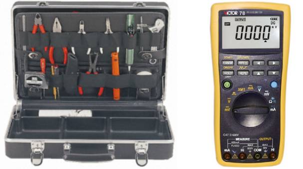
Instrument Workshop Tool List
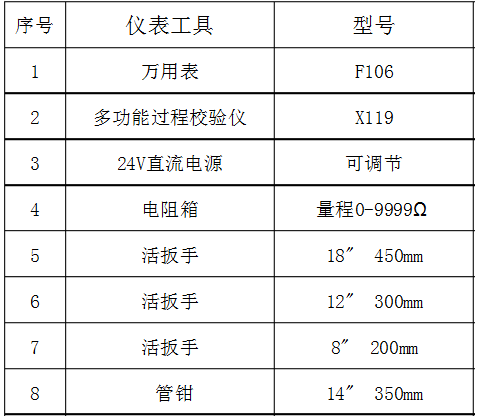
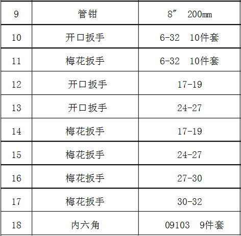
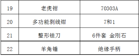
Tool Details 1. Screwdriver
A screwdriver, also known as a driver or a flathead screwdriver, has two common head shapes: flat and Phillips. The flat screwdriver is used to tighten or remove screws with a flat slot, while the Phillips screwdriver is specifically for tightening or removing screws with a cross slot.
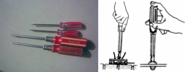
Usage Precautions:
-
Select a suitable screwdriver size based on the screw size; do not use it as a lever to avoid damaging the tool or screw.
-
When working with electricity, avoid touching the metal shaft of the screwdriver to prevent electric shock.
-
To prevent the metal shaft from touching the body or nearby live parts, the metal shaft should be covered with an insulating tube.
2. Wire Pliers
Wire pliers, also known as tiger pliers or needle-nose pliers, are shown in the image. They are used to grip, hold, twist, bend, or cut metal wires. Wire pliers come with insulated handles, and the common sizes are 150mm, 175mm, and 200mm; the insulation can withstand up to 500V, so they are only suitable for low-voltage live equipment.

Usage Precautions:
-
Before use, check the insulation of the wire pliers to prevent electric shock during live work.
-
When cutting live wires, do not cut two wires of different potentials (e.g., phase wire and neutral wire) simultaneously to avoid short-circuit accidents.
3. Needle-Nose Pliers
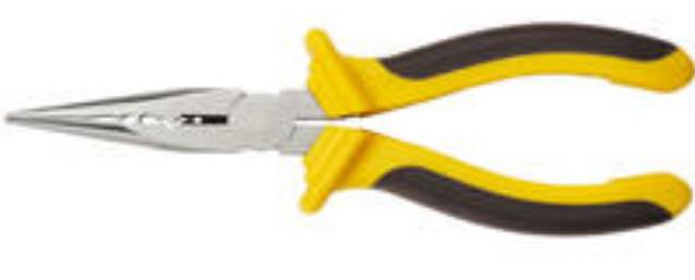
Needle-nose pliers have a pointed head, suitable for narrow working spaces or low-voltage electrical operations. They can also be used to cut small metal wires and are flexible for making or repairing instrument wire connections. When choosing needle-nose pliers, opt for those with insulated handles and acid-resistant plastic sheaths, rated for over 500V. Common sizes include 130mm, 160mm, 180mm, and 200mm.
4. Wire Strippers
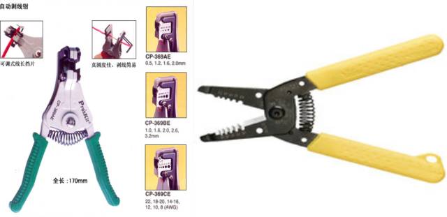
Wire strippers are specialized tools used to strip the insulation from small diameter wires, as shown in the image. They have insulated handles, rated for 500V, and come in manual and automatic types.
Automatic: Adapts to the internal wire size, preventing damage to the internal wire; the stripping length is adjustable.
5. Diagonal Cutting Pliers
Diagonal cutting pliers are also commonly used for repairs; their head is flat and slanted, also known as flat-nose pliers, primarily used for cutting wires, excess leads from components, and often used to cut insulation sleeves, nylon ties, etc. They have iron handles and insulated tube sheaths. Common diagonal cutting pliers should have insulated handles rated for over 1000V.
6. Electrician’s Knife
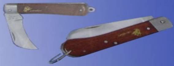
The electrician’s knife, as shown in the image, is suitable for cutting wire insulation, wooden stakes, and ropes during assembly and maintenance work. Electrician’s knives are available in large (112mm) and small (88mm) blade sizes.
Usage Precautions:
-
Do not use for live work to avoid electric shock.
-
Always cut with the blade facing outward and avoid injuring your fingers.
-
When cutting wire insulation, the knife edge should be at a small acute angle to the wire to avoid cutting the wire itself.
-
After use, immediately retract the blade into the handle.
7. Adjustable Wrench
The adjustable wrench, also known as a crescent wrench, is a specialized tool used to tighten and loosen nuts. The adjustable wrench consists of a head and a handle; the head includes an adjustable jaw, fixed jaw, worm gear, and axle pin, as shown in the image. Turning the worm gear adjusts the jaw size.
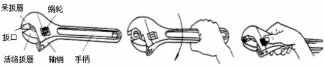
Usage Precautions:
-
Do not use the adjustable wrench in reverse to avoid damaging the adjustable jaw.
-
Do not use a lever to extend the handle for increased torque.
-
Do not use it as a pry bar or hammer.
8. Voltage Tester
Also known as a test pen, it is a commonly used auxiliary safety tool. It is used to check whether conductors or various electrical devices below 500V are live. It is portable, and as long as you understand the principle of the voltage tester, it can be flexibly applied with familiar circuit knowledge.
There are two common types:
The voltage tester should not be held like a pen when writing. The correct grip is to press the end of the voltage tester against the palm or hold it with the index finger while pinching the body with the other fingers. 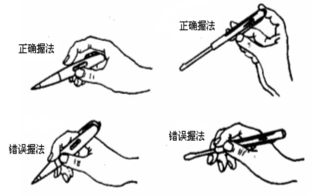
Functions of the Pen
-
Distinguish between AC and DC. When AC passes through the tester, both electrodes in the neon bulb will light up simultaneously, whereas only one electrode lights up when DC passes through.
-
Determine the positive and negative poles of DC. When the tester is connected across the positive and negative poles of a DC circuit, the end that lights up is the negative pole, and the end that does not light up is the positive pole.
-
Used as a neutral line monitor. If one end of the tester is connected to the neutral line and the other end is connected to the ground, the neon bulb will light up if the neutral line is broken; if not, it will not light up.
-
Determine whether an object is charged with static electricity. If the tester touches the object and the neon bulb lights up, the object is charged.
Usage Precautions:
-
Before using the voltage tester, first check whether there is a safety resistor inside; visually inspect for any damage, moisture, or water ingress. Only use it after passing the inspection.
-
Do not touch the metal probe at the front end of the tester with your hand, as this may cause electric shock.
-
When using the voltage tester, be sure to touch the metal part at the tail end; otherwise, without forming a circuit with the live body, the neon bulb will not light up, leading to a false judgment that the live body is not live, which is very dangerous.
-
Before measuring whether electrical equipment is live, first test the voltage tester on a known power source to check if the neon bulb lights up normally. If it does, then you can use it.
-
When testing a live body in bright light, pay special attention to whether the neon bulb is truly lighting up (or not lighting up); if necessary, use another hand to block the light for careful judgment. Never make a false judgment that the neon bulb is not lighting up when it is, and mistakenly believe that the live body is not live.
-
If the neon bulb glows weakly, do not conclude that the live body voltage is not high enough; it may be that the tester or testing point is dirty, or you may be testing the live body’s ground wire. In this case, clean the tester or select a new testing point. If after repeated tests the neon bulb still does not light up or glows weakly, only then can you determine that the test body is indeed not live.
9. Multimeter
A multimeter, also known as a multifunction meter, is a versatile measuring instrument that can generally measure DC current, DC voltage, AC voltage, resistance, frequency, AC current, capacitance, etc.
There are mainly two common types: digital multimeters and analog multimeters. Digital measuring instruments have become mainstream and are replacing analog instruments. Compared to analog instruments, digital instruments have higher sensitivity, accuracy, clear display, strong overload capacity, are portable, and easier to use.
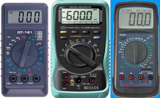
Before using the digital multimeter:
-
Carefully read the relevant user manual and familiarize yourself with the power switch, range switch, jacks, and the functions of special jacks.
-
Set the ON/OFF switch to ON, check the 9V battery; if the battery voltage is insufficient, it will be displayed on the screen, and then the battery needs to be replaced. If the display does not show anything, follow the steps below.
-
The symbols next to the test lead jacks indicate that the input voltage or current should not exceed the indicated value to protect the internal circuit from damage.
-
Before testing, the function switch should be set to the required range.
-
The red probe is positive, and the black probe is negative; pay attention to the polarity of the probes.
Multimeter Usage Tips:
Correctly using a multimeter can not only quickly and accurately identify the fault location but also prevent damage to electrical devices and the multimeter itself.
(1) Measure first, check the range; do not measure without checking
Every time you pick up the probes to prepare for measurement, always double-check whether the measurement category and range selection switch are set correctly. For safety, this habit must be developed.
(2) Do not change the range during measurement; switch to the off position after measuring
Do not arbitrarily adjust the selection knob during measurement, especially when measuring high voltage (e.g., 220V) or large current (e.g., 0.5A) to avoid arcing and damaging the switch contacts. After completing the measurement, set the range selection switch to the “•” position.
(3) The dial should be level, and readings should be aligned
When using a multimeter, it should be rotated horizontally, and the line of sight should be directly aligned with the pointer when reading.
(4) The range should be appropriate, with the pointer deflected over half
When selecting a range, if the size of the measurement cannot be estimated in advance, select a larger range first, then gradually switch to a smaller range based on the deflection angle until the pointer deflects to about two-thirds of the full scale.
(5) Measure resistance without voltage; discharge capacitors before measuring
It is strictly prohibited to measure resistance in a live circuit. When checking large capacitors on electrical devices, short-circuit and discharge the capacitor before measuring.
(6) Zero the measurement before switching ranges
When measuring resistance, first set the switch to the resistance range, short the two probes, and adjust the “Ω” zero potentiometer until the pointer points to zero ohms before measuring. Each time the resistance range is changed, the ohm zero point should be readjusted.
(7) Remember the black negative; the black probe connects to “+” inside the meter
The red probe is positive, and the black probe is negative, but in the resistance range, the black probe connects to the positive terminal of the internal battery.
(8) Measure current in series; measure voltage in parallel
When measuring current, the multimeter should be connected in series in the circuit being measured; when measuring voltage, it should be connected in parallel across the two terminals of the circuit being measured.
(9) Do not reverse polarity; develop a habit of using one hand
When measuring current and voltage, pay special attention to ensure that the polarity of the red and black probes is not reversed, and develop a habit of using one hand for safety.

 Public WeChat ID: Dongying Safety Supervision Bureau
 Public Weibo: Safety Dongying Long press the QR code to follow us