Hello everyone, in the last video we shared the decoding of the 1-wire protocol, today let’s take a look at its trigger function.
Once the protocol trigger is turned on in the decoding module, after pressing the [Trigger] button, the trigger type automatically changes to the decoded 1-wire protocol. Set the trigger mode to normal, and in the protocol parameters, you can set the trigger parameters for the 1-wire protocol. The trigger source is set according to the actual input channel. The speed modes include standard and drive modes; in drive mode, the data transfer rate is slightly higher than in standard mode, so we choose standard mode.
The trigger modes include start segment trigger, instruction trigger, and custom trigger. To set a custom trigger, long-press knob A to get the help information for instruction 1. Instruction 1 refers to the 8-bit instruction of the first input to be triggered. When you are unclear about a certain setting, you can select it first and long-press the corresponding knob to view its help information. Set instruction 1 to 0xCC and instruction 2 to 0x01. After determining both instructions, set the interval bit width to 16 bits.
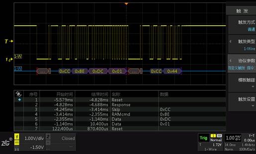
Figure 1: Custom Trigger for 1-Wire Protocol
Returning to the main interface, you can see that the trigger point has been accurately located at the end of 0x01. In the decoding environment, observing the protocol trigger situation is more beneficial for protocol analysis!