




Summary of Circuit Board Repair Techniques
Fault Characteristics and Repair of Capacitor Damage in Engineering Circuit Boards
Capacitor damage causes the highest rate of failures in electronic devices, with the failure of electrolytic capacitors being the most common.
Capacitor damage manifests as: 1. Reduced capacitance; 2. Complete loss of capacitance; 3. Leakage; 4. Short circuit.
Since capacitors serve different functions in circuits, the faults they cause also have distinct characteristics. In industrial control circuit boards, digital circuits dominate, and capacitors are mostly used for power filtering, with fewer used for signal coupling and oscillation circuits. If the electrolytic capacitor used in a switching power supply is damaged, the switching power supply may not oscillate, resulting in no voltage output; or the output voltage may not be filtered properly, causing unstable voltage and logical confusion in the circuit, which manifests as the machine working intermittently or failing to start. If the capacitor is between the positive and negative terminals of the digital circuit power supply, the fault presents similarly.
This is especially evident on computer motherboards, where many computers show symptoms of being unable to start sometimes after a few years of use. Opening the case often reveals bulging electrolytic capacitors. If the capacitor is removed and measured for capacitance, it is often found to be significantly lower than its actual value.
The lifespan of a capacitor is directly related to the ambient temperature; the higher the ambient temperature, the shorter the capacitor’s lifespan. This rule applies not only to electrolytic capacitors but also to other types of capacitors. Therefore, when searching for faulty capacitors, one should focus on those located close to heat sources, such as near heat sinks and high-power components; the closer they are, the higher the likelihood of damage.
I once repaired a power supply for an X-ray flaw detector, where the user reported smoke coming from the power supply. Upon opening the case, I found a large 1000uF/350V capacitor leaking a viscous substance. After removing it, I measured its capacitance and found it to be only a few dozen uF. I also noticed that this capacitor was the only one close to the rectifier bridge’s heat sink, while others farther away were intact and had normal capacitance. Additionally, I found a ceramic capacitor that had shorted, which was also located near a heated component. Therefore, emphasis should be placed on proximity when troubleshooting.
Some capacitors with severe leakage can even feel hot to the touch, and these capacitors must be replaced.
When troubleshooting intermittent faults, if the possibility of poor contact has been ruled out, most failures are generally caused by capacitor damage. Therefore, when encountering such faults, it is advisable to examine the capacitors closely; replacing them often yields surprising results (of course, attention should also be paid to capacitor quality, choosing reputable brands like Rubycon or Black Diamond).
Characteristics and Identification of Resistor Damage
Many beginners often struggle with resistors during circuit repairs, dismantling and soldering repeatedly. However, with experience, understanding the characteristics of resistor damage can save a lot of effort.
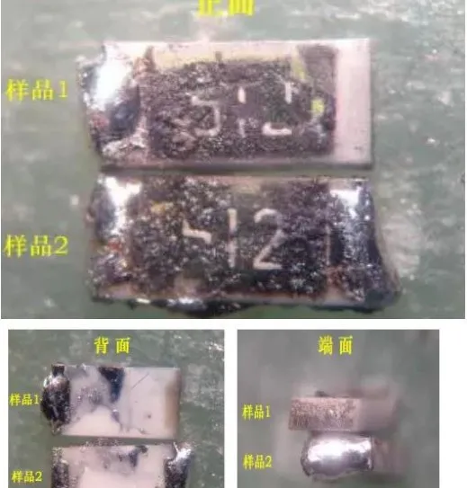
Resistors are the most numerous components in electrical devices, but they are not the components with the highest failure rate. Resistor damage is most commonly open circuit, while an increase in resistance is less common, and a decrease in resistance is very rare. Common types include carbon film resistors, metal film resistors, wire-wound resistors, and fusible resistors.
The first two types of resistors are most widely used, and their failure characteristics are that low resistance (below 100Ω) and high resistance (above 100kΩ) have a higher failure rate, while mid-range resistances (such as hundreds of ohms to tens of kilohms) rarely fail. Low resistance resistors often show signs of burning and blackening when damaged, making them easy to identify, while high resistance resistors usually show little or no evidence of damage.
Wire-wound resistors are generally used for high current limiting and have relatively low resistance values. When cylindrical wire-wound resistors fail, some may blacken or show surface peeling or cracking, while others may show no visible signs. Cement resistors, a type of wire-wound resistor, may break when damaged, otherwise showing no visible signs. Fusible resistors may have a section of their surface blown off when they fail, but they will never show signs of burning or blackening.
Based on the characteristics listed above, we can first observe whether there are signs of burning on low resistance resistors on the circuit board. Then, according to the characteristics that most resistor failures are open circuits or increased resistance, and that high resistance resistors are more prone to failure, we can use a multimeter to directly measure the resistance across the terminals of high resistance resistors on the circuit board. If the measured resistance is higher than the nominal value, that resistor is definitely damaged (note that the conclusion should be drawn only after the resistance value stabilizes, as there may be parallel capacitor elements in the circuit causing a charging and discharging process). If the measured resistance is lower than the nominal value, it is generally not worth considering. By measuring every resistor on the circuit board this way, even if one thousand resistors are wrongly identified, none will be overlooked.
Methods for Judging the Quality of Operational Amplifiers
Determining the quality of operational amplifiers can be challenging for many electronic repair technicians, not just due to their educational background (I have many undergraduates who wouldn’t understand without teaching, and even when taught, it takes a long time to grasp, and I have a graduate student specializing in frequency control who is similarly challenged!). Here, I would like to discuss this with everyone, hoping to be of assistance.
An ideal operational amplifier has the characteristics of “virtual short” and “virtual open,” which are very useful for analyzing linear applications of operational amplifier circuits. To ensure linear applications, the operational amplifier must operate under closed-loop (negative feedback). Without negative feedback, the open-loop operational amplifier becomes a comparator.
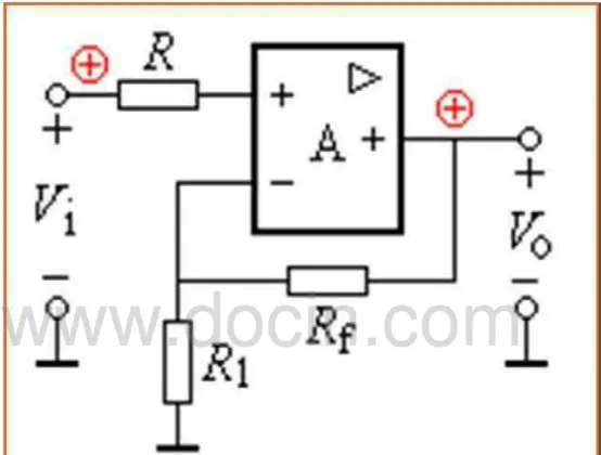
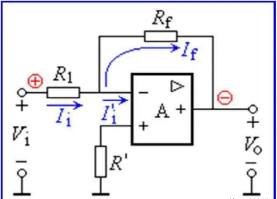
From the images, we can see that regardless of the type of amplifier, there is a feedback resistor Rf. Thus, when repairing, we can check this feedback resistor on the circuit, using a multimeter to measure the resistance between the output and the inverting input. If it is abnormally high, such as above several MΩ, we can reasonably conclude that the device is used as a comparator; if this resistance is relatively low (0Ω to tens of kΩ), we should check if there is a resistor connecting the output and inverting input; if so, it is definitely used as an amplifier.
According to the principle of virtual short in amplifiers, if this operational amplifier is functioning normally, the voltages at the non-inverting and inverting input terminals must be equal, even if there is a difference, it should be in the mV range. Of course, in some high input impedance circuits, the internal resistance of the multimeter may slightly affect the voltage measurement, but generally, it should not exceed 0.2V. If there is a difference of more than 0.5V, the amplifier is undoubtedly faulty! (I used a FLUKE179 multimeter).
If the device is used as a comparator, then the non-inverting and inverting input voltages are allowed to be unequal.
If the non-inverting voltage > inverting voltage, the output voltage approaches the positive maximum value; if the non-inverting voltage < inverting voltage, the output voltage approaches 0V or the negative maximum value (depending on whether it is a dual or single power supply). If the detected voltage does not conform to this rule, the device is undoubtedly faulty! Thus, you do not need to use substitution methods or remove the chip from the circuit board to determine the quality of the operational amplifier.
A Small Eraser Solving Big Problems
With the increasing use of industrial control boards, many boards utilize gold fingers inserted into slots. Due to the harsh industrial environment, which is often dusty, humid, and full of corrosive gases, boards can easily suffer from contact failure. Many friends may have solved the problem by replacing the board, but the cost of purchasing new boards can be substantial, especially for certain imported equipment. In fact, you might consider using an eraser to repeatedly clean the gold fingers, removing dirt, and then testing the device again; it might just solve the problem! This method is simple and practical.
Analysis of Intermittent Electrical Faults
Intermittent electrical faults can generally be categorized into the following situations based on probability:
1. Poor contact
Contact failures between the board and slots, internal breaks in cables, poor contact at plugs and terminals, and cold solder joints are all included in this category;
2. Signal interference
For digital circuits, faults may only present under specific conditions; it is possible that excessive interference affects the control system, causing errors. There may also be changes in individual component parameters or overall performance parameters on the circuit board, leading to a decrease in anti-interference capability, resulting in faults;
3. Poor thermal stability of components
From extensive repair experience, the most common issue is the poor thermal stability of electrolytic capacitors, followed by other capacitors, transistors, diodes, ICs, and resistors;
4. Moisture and dust on the circuit board.
Moisture and dust can conduct electricity, creating resistance effects, and during thermal expansion and contraction, the resistance value may change. This resistance can have a parallel effect with other components, and when this effect is significant, it can alter circuit parameters, leading to faults.


Please follow the WeChat public platform of Beijing Weishi Xingbang Technology to get more exciting information!
Customer Service Hotline: 010-62910568