1. Wiring according to the diagram is the highest principle and should not be overlooked.First, before wiring, it is essential to carefully read the drawings and fully understand the designer’s intentions, rather than relying on personal so-called rich experience. If any unclear or contradictory points are found, the designer should be contacted immediately for confirmation before proceeding with the wiring construction.
2. The wiring sequence should be clear and straightforward, with checkability. This is rarely achieved in practice, as it often ends up being just connecting wires and closing the box.
3. Learn wiring techniques and be adept at using professional tools flexibly. For example:
Q: When making a PLC cabinet, there are many wiring boards and terminals. If not handled properly, there can be looseness, burrs, etc. Should we strip the wire and press it in directly, use pins, or solder?
A: For single-core wires, strip and press directly; for multi-core wires, use cold-pressed terminals, soldering is not recommended.
Q: When there are many expansion modules for the PLC, how should the common and power terminals be handled? Should they be directly paralleled to the next module on each PLC module’s terminal, or connected to terminals and shorted on the terminal block?
A: In field maintenance, we prefer to distribute the power supply at the terminals and lead them to user points (using wire number tubes or marking the terminals to indicate the destination). This is intuitive and minimizes mutual interference. We do not want to connect multiple wires from one point to another, nor do we want more than two wires connected under one terminal. For power terminal blocks, we prefer using terminals with fuses or those that can disconnect connections between terminals, which is very convenient for troubleshooting short circuits.
01PLC Internal and External Circuits
1. External Circuit Wiring
Figure 1 shows the electrical control circuit for full-voltage starting of a motor, where the control logic is implemented through the AC contactor KM coil, indicator lights HL1, HL2, normally closed contacts of thermal relays FR, stop button SB2, start button SB1, and normally open auxiliary contacts KM connected by wires.
When QS is closed and the start button SB1 is pressed, the coil KM is energized and self-locks, connecting the auxiliary contact KM in the branch of the indicator light HL1 and the main contact in the main circuit, causing HL1 to light up and the motor M to start. When the stop button SB2 is pressed, the coil KM is de-energized, HL1 goes out, and M stops.
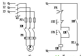
▲Figure 1 Electrical control circuit for full-voltage starting of a motor
Figure 2 is the external wiring diagram for full-voltage starting control of a motor using a SIEMENS S7 series PLC. The main circuit remains unchanged, while the normally closed contacts of the thermal relay FR, stop button SB2, start button SB1, etc., are connected to the PLC’s input interface as input devices, and the AC contactor KM coil, indicator lights HL1, HL2, etc., are connected to the PLC’s output interface as output devices. The control logic is implemented through a user program written and stored in the program memory according to the requirements for full-voltage control of the motor.
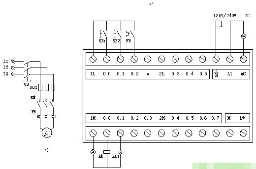
▲Figure 2 PLC control wiring diagram for full-voltage starting of a motor
2. Establishing the Internal I/O Image Area
An I/O image storage area is opened in the PLC memory to store the status of I/O signals, referred to as input image registers and output image registers. Additionally, other programming elements in the PLC also have corresponding image storage areas, known as element image registers.
The size of the I/O image area is determined by the PLC’s system program. For each input point in the system, there is always a corresponding bit in the input image area, and for each output point in the system, there is also a corresponding bit in the output image area. The addressing numbers of the system’s input and output points correspond to the address numbers of the I/O image area.
When the PLC operates, the collected input signal status is stored in the corresponding bit of the input image area, and the calculation results are stored in the corresponding bit of the output image area. The data required to describe the equivalent contacts of input relays or the equivalent states of output relays during the execution of the user program is taken from the I/O image area, rather than directly interacting with external devices.
The establishment of the I/O image area allows the PLC to only interact with the status data stored in the memory address units during operation, and the system output only sets a status data for a specific memory address unit. This not only speeds up program execution but also isolates the control system from the outside world, enhancing the system’s anti-interference capability.
3. Internal Equivalent Circuit
Figure 3 shows the internal equivalent circuit of the PLC. Taking the start button SB1 as an example, its input interface I0.0 is connected to a trigger I0.0 in the input image area. When SB1 is activated, the trigger I0.0 is triggered to a “1” state, and this “1” state can be directly referenced by the user program as the state of the I0.0 contact. At this time, the state of the I0.0 contact is the same as the on/off state of SB1; if SB1 is on, the state of the I0.0 contact is “1”; conversely, if SB1 is off, the state of the I0.0 contact is “0”;
Since the function of the I0.0 trigger is the same as that of a relay coil and does not require hard-wired connections, the I0.0 trigger is equivalent to a soft relay coil I0.0 inside the PLC. Directly referencing the state of the I0.0 coil results in the I0.0 contact being equivalent to a normally open contact (also known as a dynamic contact) controlled by the I0.0 coil.
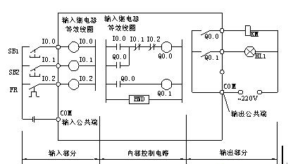
▲Figure 3 Internal equivalent circuit of the PLC
Similarly, the stop button SB2 is connected to a soft relay coil I0.1 inside the PLC. When SB2 is closed, the state of the I0.1 coil is “1”; conversely, it is “0”. The state of the relay coil I0.1 is inverted by the user program and referenced as the state of the I0.1 contact, so I0.1 is equivalent to a normally closed contact (also known as a dynamic break contact) controlled by the I0.1 coil. The output contacts Q0.0 and Q0.1 are the physical normally open contacts of the PLC’s internal relays, which, when closed, will energize the corresponding KM coil and indicator light HL1. The PLC output terminal has a common interface COM for the output power.
02PLC Control System
Using a PLC to implement the electrical control system for full-voltage starting of a motor, the main circuit remains essentially unchanged, while the PLC replaces the electrical control circuit.
1. Composition of the PLC Control System
Figure 4 is a basic composition diagram of the PLC control system for full-voltage starting of a motor, which can be divided into three parts: input circuit, internal control circuit, and output circuit.
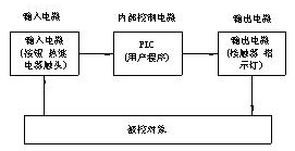
▲Figure 4 Basic composition diagram of the PLC control system
Input Circuit
The function of the input circuit is to send input control signals to the PLC. The input devices are buttons SB1, SB2, and the normally closed contact of FR. The external input control signals are input into the corresponding input relay in the PLC, which can provide any number of normally open and normally closed contacts for programming use in the PLC internal control circuit.
Output Circuit
The function of the output circuit is to convert the PLC’s output control signals into signals capable of driving the KM coil and indicator light HL1. The internal control circuit of the PLC contains many output relays, each of which, in addition to providing normally open and normally closed contacts for programming use in the PLC internal control circuit, also provides a normally open contact connected to the output port, known as an internal hard contact, which is an internal physical normally open contact. This contact drives external loads such as the KM coil and HL1 indicator light, while the KM coil controls the starting and stopping of the motor M through the main contact in the main circuit. The power supply for driving the load is provided by an external power source, and the PLC output port also has a common terminal COM for the output power.
Internal Control Circuit
The internal control circuit is formed by the user program written according to the actual control requirements of the motor being controlled. Its function is to calculate, process, and judge the status of input and output signals according to the logical relationships specified in the user program, and then obtain the corresponding output control signals to drive output devices such as motor M and indicator light HL1.
The user program is input into the PLC’s user program memory through communication with a personal computer or programming device. Modifications to the user program only require changing certain statements in the memory through programming devices, without altering the internal wiring of the controller, achieving flexibility in control.
2. PLC Control Ladder Diagram
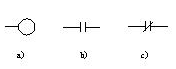
The ladder diagram is a representation that equivalently models the PLC as a control circuit composed of many internal relay coils, normally open contacts, normally closed contacts, or functional program blocks. Figure 5 shows the commonly used equivalent control element symbols in PLC ladder diagrams.
▲Figure 5 Commonly used equivalent control element symbols in ladder diagrams
a) Coil b) Normally open contact c) Normally closed contact
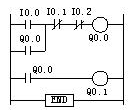
Figure 6 is the PLC control ladder diagram for full-voltage starting of a motor, composed of the normally closed contact FR, normally closed button SB2, normally open auxiliary contact KM, and normally open button SB1 in a parallel unit, along with the KM coil. The full-voltage starting control ladder diagram is similar in form to the electrical control circuit diagram but has many differences from it.
▲Figure 6 Ladder diagram for full-voltage starting control of a motor
The physical structure of relay elements in ladder diagrams differs from that of electrical elements.
The coils and contacts in ladder diagrams are functionally equivalent to the coils and contacts of electrical elements. However, in physical terms, the coils and contacts in ladder diagrams are merely storage bits in the input and output memory, differing from the physical structure of electrical elements.
The on/off states of relay elements in ladder diagrams differ from those of electrical elements.
The on/off states of relay elements in ladder diagrams are related to the data stored in the corresponding storage bits. If the data in that storage bit is “1”, the element is in the “on” state; if the data is “0”, it indicates the “off” state, which differs from the actual on/off states of electrical elements.
The state switching process of relay elements in ladder diagrams differs from that of electrical elements.
The state switching of relay elements in ladder diagrams is merely an operation on the status data of storage bits. If the PLC assigns the data of the normally open contact equivalent storage bit to “1”, the dynamic connection operation is completed. Similarly, if the data of the normally closed contact equivalent storage bit is assigned to “0”, the dynamic disconnection operation is completed. The switching operation process has no time delay. In contrast, the dynamic connection or disconnection switching of electrical element coils and contacts must have a time delay and generally requires a process of first disconnecting and then closing.
The number of contacts belonging to relay elements in ladder diagrams differs from that of electrical elements.
If the PLC retrieves the bit data “0” from the corresponding storage bit of the input relay I0.0 and stores it in another storage bit, the stored bit becomes a normally open contact controlled by the I0.0 relay, with the stored data being “0”. If, after retrieving the bit data “0”, an inversion operation is performed before storing it in a storage bit, the stored data will be “1”, and that storage bit will become a normally closed contact controlled by the I0.0 relay.
As long as the PLC’s internal memory is sufficient, this bit data transfer operation can be performed infinitely, and each operation can generate a relay contact in the ladder diagram. Thus, the relay contacts in ladder diagrams can, in principle, be reused infinitely. However, the coils in the PLC can usually only be referenced once; if the same address number coil needs to be reused, it should be done with caution. Unlike PLCs, the number of contacts in electrical elements is limited.
The drawing rule for each row in the ladder diagram is to start from the left bus, pass through contacts and coils (or functional blocks), and terminate at the right bus. Generally, parallel units are drawn on the left side of each row, and output coils are drawn on the right side, with other series elements drawn in the middle.
Disclaimer: The articles published by this account are for learning and communication purposes only, with no commercial use. Copyright belongs to the original author, and we pay tribute to the original author. We apologize for any infringement due to the inability to find the original author for some articles that have been reprinted multiple times. If there is any infringement, please inform us, and we will delete it promptly. Please indicate the source when reprinting.
Source: Electrical Engineering Learning