1. Internal Structure of PLC
Currently, the mainstream PLC brands include Siemens (Germany), Mitsubishi (Japan), Omron (Japan), Schneider (France), etc. Different brands use different programming software, and even different models of the same brand may use different software. For example, Siemens PLC has four programming software options: STEP 7 Microwin (S7-200), STEP 7- Micro/WIN SMART (specifically developed for S7-200 SMART), STEP7 V5.5 (S7-300, S7-400, ET200), and TIA Portal (S7-300, S7-400, S7-1500, S7-1200).
Although there are many types of PLCs with varying performance, their composition and working principles are almost the same or similar. A PLC is essentially an industrial control computer, composed of hardware and software, just like a general-purpose computer. Now, let’s introduce the hardware of PLCs.
PLCs can be categorized into two structural types: integrated and modular. Regardless of the structural type, their basic components and functions are the same. The basic components of PLC hardware include the Central Processing Unit (CPU), memory, input/output interfaces (I/O interfaces), I/O expansion interfaces, communication interfaces, and power supply, as shown in Figure 1-15. If you are unfamiliar with the components of a PLC, let’s compare it to our mobile phones. A mobile phone performs calculations and controls the flash light, which requires the phone’s CPU to work, similar to the role of the PLC’s CPU; mobile phones have memory for storing images and videos, which corresponds to the PLC’s memory; the I/O interfaces, communication interfaces, and power supply of the PLC can also be matched with corresponding components in a phone or computer.
Central Processing Unit (CPU)
The CPU directs the PLC to operate in an orderly manner according to the system program. In summary, the main functions of the CPU include the following aspects:
1) Receiving and storing user programs and data input from the programmer.
2) Diagnosing power supply and internal circuit faults of the PLC, and checking for syntax errors in the user program.
3) Receiving the status or data from various input devices in the field in a scanning manner, and storing it in the input process image register and data memory.
4) After entering the run mode, sequentially reading, interpreting, and executing the user program, completing various operations specified by the user program, and storing the results in the output process image register or data memory.
5) Updating the status of relevant flags based on the calculation results, refreshing the contents of the output process image register, and then implementing output control, printing, or data communication through output devices.
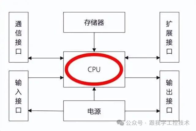
Figure 1-15 Basic Components of PLC Hardware
Memory
PLCs have Random Access Memory (RAM), Read-Only Memory (ROM), and Electrically Erasable Programmable Read-Only Memory (EEPROM). Depending on their purpose, the memory in a PLC can be divided into system program memory and user program memory. The system program memory is used to store the system program, which cannot be changed by the user and is generally ROM. The user program memory is used to store user programs and working data, which need to be frequently modified, so it is mostly RAM or EEPROM that can be read and written at any time. Since data in RAM is lost when power is off, a backup battery (lithium battery) is needed for protection. More advanced PLCs use Flash Memory as the user program memory, eliminating the need for a backup battery.
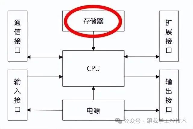
Figure 1-15 Basic Components of PLC Hardware
Input/Output Interfaces (I/O Interfaces)
The input/output interface, also known as the input/output unit, is the connecting component between the PLC and the industrial production site.
1) Input Interface
The function of the input interface is to convert the signals (digital or analog signals) sent from user input devices (such as buttons, limit switches, proximity switches, sensors, and their corresponding transmitters) into signals that the CPU can receive and process, and send them to the input process image register.
The input interface circuit is mainly used to convert the received external input signals into signals that the PLC’s internal CPU can accept for processing. To prevent erroneous input signals caused by contact bounce or interference pulses, the input interface circuit must have strong anti-interference capability. The methods to enhance the anti-interference capability of the input interface circuit mainly include:
1) Using optocouplers to improve anti-interference capability;
2) Using RC filter circuits to improve anti-interference capability.
2) Output Interface
The function of the output interface is to convert the signals processed by the CPU into the driving signals (digital or analog signals) required by external output devices, to drive various actuators (such as relays, contactors, alarms, solenoid valves, control valves, speed control devices, etc.).
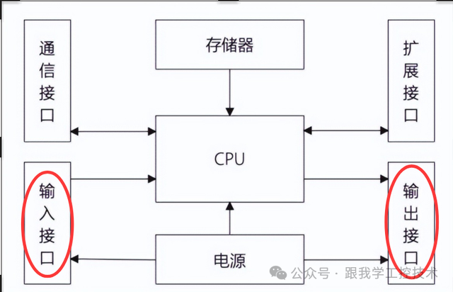
Figure 1-15 Basic Components of PLC Hardware
2. Working Principle of PLC
After powering on, the PLC needs to perform some initialization work for both hardware and software. To ensure that the PLC’s output can respond promptly to various input signals, after initialization, the PLC continuously processes various tasks in stages; this repetitive cycle of work is called the cyclic scanning working mode.
For the S7-200 PLC, a complete scanning process generally includes five stages: input sampling, executing the user program, processing communication requests, executing CPU self-diagnosis, and output refreshing, as shown in Figure 1-16. Among these, input sampling, executing the user program, and output sampling are all performed using a centralized batch processing method.
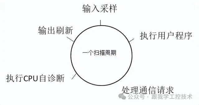
Figure 1-16 PLC Cyclic Scanning Working Mode
(1) Input SamplingInput sampling, also known as reading inputs, is the first centralized batch processing process. At the beginning of each scanning cycle, the CPU samples the current input values from all input terminals and stores them in the corresponding input process image registers in memory. At this time, the input process image registers are refreshed, and the unused bits in the input process image registers are cleared. After this, the input process image registers are isolated from the external world; regardless of how the input signals change, they will not affect the input process image registers, and their contents will remain until the next scanning cycle’s input sampling stage is refreshed.
(2) Executing User ProgramThe executing user program stage is the second centralized batch processing process. The user program of the PLC consists of several instructions arranged in order in memory. The CPU executes the user program starting from the first instruction and continues sequentially until the last instruction (end instruction) is reached (except for program interruptions or jumps). For ladder diagram programs, the scanning operation is performed in a top-to-bottom, left-to-right order.
(3) Processing Communication RequestsThe CPU processes any information received from the communication port to complete data communication tasks, checking for communication requests from computers or programmers, and processing them accordingly.
(4) Executing CPU Self-DiagnosisIn this stage, the CPU checks the status of its hardware and all I/O modules. In RUN mode, it also checks the user program memory. If a fault is detected, the fault indicator will light up, and the nature of the fault will be determined; if no fault is found, it proceeds to the next step.
(5) Output RefreshAlso known as the write output stage, this is the third centralized batch processing process. During the current scanning cycle, after the CPU completes the execution of the user program, it will output the “0” or “1” states presented by each output process image register and save them in the output latches (the data in the latches remains constant during a scanning cycle).
3. Classification of PLCs
Currently, there are two common classification methods for PLCs: one is based on structural form, and the other is based on the number of digital I/O points.
(1) Classification by Structural FormAccording to different structural forms, PLCs can be divided into integrated and modular types.
1) Integrated PLCThe basic structure of an integrated PLC is as shown in Figure 1-17. It integrates the power supply, CPU, memory, I/O interfaces, communication interfaces, and I/O expansion interfaces into one shell, forming a whole, commonly referred to as the PLC main unit or basic unit. Users can input digital or analog signals (analog signals need to be converted via A/D) from input devices such as buttons, switches, or various sensors and corresponding transmitters into the input interface, which are then stored in the input process image register of the main unit’s memory. After processing by the CPU, control signals for digital or analog outputs (analog signals need to be converted by the CPU via D/A) are output from the output interface to the devices to be controlled.
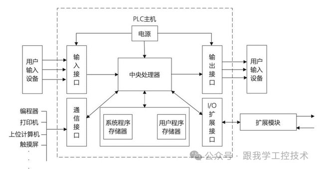
Figure 1-17 Structure of Integrated PLC
2) Modular PLCThe basic structure of a modular PLC is as illustrated in Figure 1-18. It breaks down the various components of the integrated PLC main unit into independent modules, such as CPU modules, input modules, output modules, communication modules, various intelligent I/O modules, and power supply modules, etc. These modules are connected via a bus and installed on a rack or rail.
The advantage of modular PLCs is their flexible configuration, making assembly and maintenance convenient. Generally, medium to large PLCs mostly adopt this structure, such as Siemens S7-300 and S7-400 series PLCs.
From the above, it can be seen that modular PLCs are more flexible in configuration than integrated PLCs, allowing for arbitrary selection of input and output points. Although integrated PLCs can also connect other modules through expansion interfaces, the number of expandable modules is indeed limited.
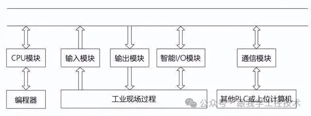
Figure 1-18 Structure of Modular PLC
(3) Classification by Number of Digital I/O PointsThe number of digital I/O points is one of the performance indicators of PLCs. Based on the number of digital I/O points, PLCs can be classified into small (low-end), medium (mid-range), and large (high-end) types, as shown in Table 1-5.
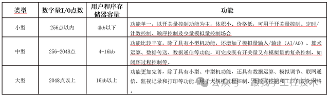
Table 1-5 Classification of I/O Points
4. Classification of Siemens PLCs
Siemens PLC – S7 series is the traditional PLC product recognized by everyone.
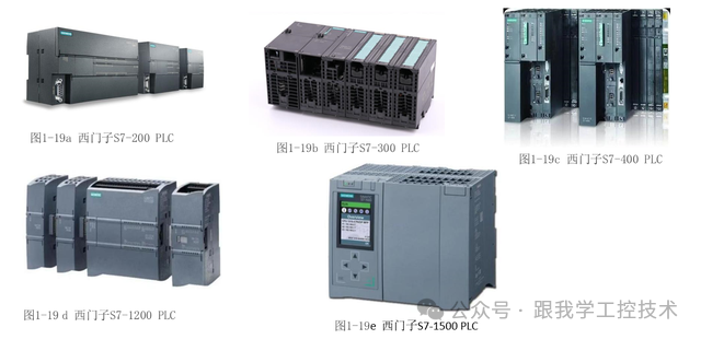
S7-200 is a compact PLC designed for applications with low performance requirements. As shown in Figure 1-19a, it integrates the power supply, Central Processing Unit (CPU), and I/O interfaces into one shell.
Siemens S7-300 is a modular medium-sized PLC that can expand up to 32 modules, belonging to a standard modular structured PLC. Various modules are independent and installed on a fixed rack (rail), forming a complete PLC application system, as shown in Figure 1-19b.
S7-400 is a large PLC that can expand over 300 modules. S7-300/400 can also form MPI, PROFIBUS, and Industrial Ethernet networks, as illustrated in Figure 1-19c.
M7-300/400 has the same structure as S7-300/400, and can be used as both a CPU and a functional module. It has AT-compatible computer functionality and can be programmed using languages such as C, C++, or CFC.
S7-1200 is a newly released modular small PLC from Siemens. Its main component is the so-called CPU in the middle, which is quite sophisticated as it integrates the processor, input/output ports, and memory, allowing it to operate independently. The S7-1200 has five CPU models: 1211, 1212, 1214, 1215, and 1217. Except for 1217, which only has a DC/DC/DC version, the other models have AC/DC/RLY, DC/DC/DC, and DC/DC/RLY versions, corresponding to different power/input/output methods, making it particularly flexible, as shown in Figure 1-19d.
The new S7-1500 controller is exceptional, featuring many innovative technologies and setting new standards to maximize production efficiency. It is suitable for both small devices and complex devices that require high speed and accuracy. The S7-1500 can be seamlessly integrated into the TIA Portal, greatly enhancing engineering configuration efficiency, as shown in Figure 1-19 (e).
For more PLC knowledge, you can contact us via WeChat.