Cover Image In 2016, Mercedes-Benz once made an advertisement where the deer’s skeleton was clearly visible under the car lights (as shown above). Today’s car lights are bright enough to achieve this level.[Previous Highlights]: Beginner’s Guide: Practical Guide to Adjusting GPU on RK Platform Ubuntu
Welcome to follow “Embedded Sharing“, updated weekly! ☞
Main Content
Before Debugging
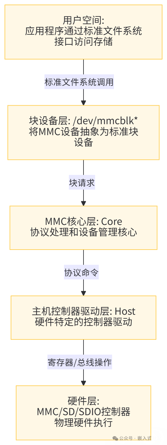
(1) Understand the MMC Subsystem
Linux provides the MMC subsystem to access various SD/MMC/EMMC/SDIO devices. The MMC subsystem can be divided into the following layers:: User Space, Block Device Layer, MMC Core Layer, Host Controller Driver Layer, Hardware Layer. The system block diagram is as follows:
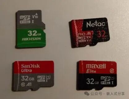
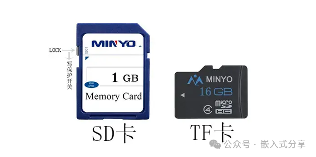
(2) Clarify TF, Micro SD, and SD Cards
- TF Card (TransFlash Card)
In 2004, Motorola and SanDisk jointly launched it, originally intended to provide ultra-small storage expansion solutions for increasingly compact mobile phones. “TransFlash” was its original name.
- Micro SD Card
In 2005, the SD Association (SDA) adopted the TransFlash standard and officially renamed it Micro SD Card. Since then, the name “TF Card” has gradually become an informal term.
- SD Card (Secure Digital Card) was first developed in 1999 by Panasonic, Toshiba, and SanDisk, aiming to replace the older MMC card (MultiMediaCard). It quickly became the mainstream storage format for cameras, camcorders, and other devices.
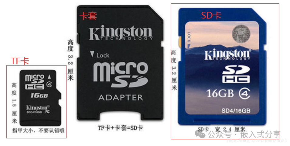
Therefore, TF Card == Micro SD Card (though many engineers still informally refer to it as “TF Card”), while the SD Card is a larger, standard-sized card. Micro SD Cards can be converted to SD Cards using an adapter.
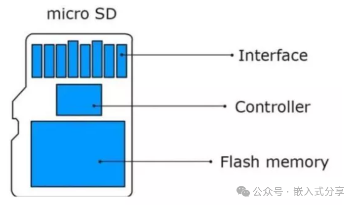
Micro SD Card
Micro SD Card (i.e., TF Card) and SD Card
Micro SD Card (i.e., TF Card) to SD Card
(3) Understand the Two Modes of Micro SD
Micro SD Cards support two optional communication protocols: SDIO and SPI bus modes, and the host system can choose either mode.
SDIO mode supports 4-bit high-performance data transmission. In SDIO mode, the Micro SD Card operates with a total of 6 signal lines (CLK, CMD, DAT0-DAT3), with a bus width of 4 bits. The SDIO bus allows dynamic configuration of the number of bidirectional data signal lines from 1 to 4.
For compatibility, when powered on, the Micro SD Card defaults to using only DAT0 for basic communication (e.g., confirming Micro SD ID, setting operating mode). After initialization, the host can modify the bus width for data transmission with the Micro SD Card.
SPI mode provides an easy, universal interface for SPI channels. In SPI mode, there are a total of 4 signal lines (CLK, CS, MOSI, MISO), with serial communication and half-duplex operation.SPI mode sacrifices performance for great universality and simplicity. It is a “compatibility mode” or “alternative option.”
How to choose a mode? The host system can choose which mode to communicate based on its capabilities (whether it has an SDIO controller) and performance requirements. After powering on, the host forces the Micro SD Card into SPI mode by pulling down the CS signal line; otherwise, the Micro SD Card defaults to SDIO mode.
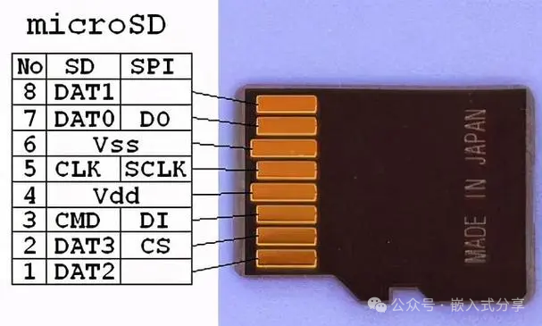
(4) Micro SD Card Pin Definitions
|
Pin Number |
Pin Name |
SDIO Mode |
SPI Mode |
|
Pin 1 |
DAT2 |
Data Line 2 |
Reserved |
|
Pin 2 |
DAT3/CS |
Data Line 3 |
Chip Select Signal |
|
Pin 3 |
CMD/MOSI |
Command Line |
Host Output, Slave Input |
|
Pin 4 |
VDD |
Power |
Power |
|
Pin 5 |
CLK |
Clock |
Clock |
|
Pin 6 |
VSS |
Power Ground |
Power Ground |
|
Pin 7 |
DAT0/MISO |
Data Line 0 |
Host Input, Slave Output |
|
Pin 8 |
DAT1 |
Data Line 1 |
Reserved |
Skip Advertisement 0.1s
Hardware Design
The SOC integrates an SDMMC controller internally, so when designing the Micro SD Card circuit, you only need to connect these interfaces to the Micro SD card socket accordingly.
It is important to note that different main controllers may have variations in circuit design; please refer to the SOC manufacturer’s data sheet for specifics. However, the interface definitions and communication principles are consistent and standard.
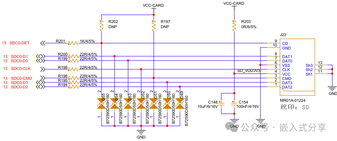
Circuit Principle:
DET: The main controller determines whether a Micro SD card is inserted by detecting the level state of the SDC0_DET pin. When the Micro SD card is inserted, the SDC0_DET pin’s contact with the shell grounds the C/D pin to a low level, indicating that a Micro SD card is inserted; otherwise, it indicates that the Micro SD card is removed.
DAT[3:0]: 4-bit data bus, allowing bidirectional communication with the host;
CLK: Clock signal, transmitting one instruction or data per clock cycle, with a frequency that can operate at any point between 0~25MHz;
CMD: Command signal or command response signal, commands are sent from the controller to the Micro SD card, which can be directed to a single Micro SD card or to all cards on the Micro SD bus; responses are the command replies sent from the storage card to the controller, which can come from a single card or all cards.
Software Configuration
Driver Path: bsp/drivers/mmc/sunxi-mmc.csys_config.fex
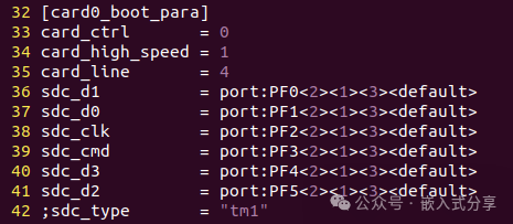
Parameter Analysis: card_ctrl: 0 selects the controller related to card production card_high_speed: speed mode 0 for low speed, 1 for high speed card_line: represents the card bus width, with options of 1, 4, 8 sdc_d1: GPIO configuration for sdc data1 sdc_d0: GPIO configuration for sdc data0 sdc_clk: GPIO configuration for sdc clk sdc_cmd: GPIO configuration for sdc cmd sdc_d3: GPIO configuration for sdc data3 sdc_d2: GPIO configuration for sdc data2dts
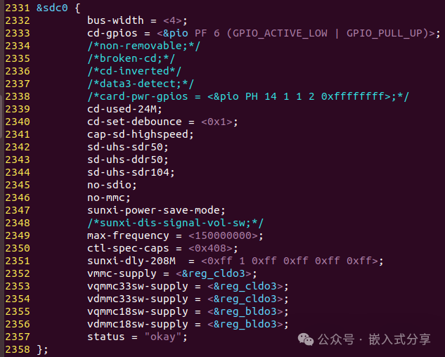
Parameter Analysis: bus-width: line width cd-gpios: GPIO configuration for card detection cd-used-24M: use 24M clock to detect card insertion/removal non-removable: non-removable broken-cd: SD card detection method: polling cd-inverted: whether the high level is valid or low level for card detection data3-detect: data3 line detection card cap-sd-highspeed: SD card high speed d-uhs-sdr50: SD card uhs-sdr50 d-uhs-ddr50: SD card uhs-ddr50 d-uhs-sdr104: SD card uhs-sdr104 no-sdio: no sdiono-mmc: no mmc sunxi-power-save-mode: clock output only when sending data or commands sunxi-dis-signal-vol-sw: turn off voltage switching max-frequency: maximum frequency ctl-spec-caps: control spec capabilities vmmc-supply: supply voltage, operating voltage, needs to be modified according to actual PMU power supply scheme vqmmc33sw-supply: 3.3V IO voltage, needs to be modified according to actual PMU power supply scheme vdmmc33sw-supply: 3.3V card detection voltage, needs to be modified according to actual PMU power supply scheme vqmmc18sw-supply: 1.8V IO voltage, needs to be modified according to actual PMU power supply scheme vdmmc18sw-supply: 1.8V card detection voltage, needs to be modified according to actual PMU power supply schemeKernel Configuration
After entering menuconfig, select “Altwinner SD/MMC Host Controller Support*” to enable the Allwinner platform MMC driver.
Skip Advertisement 0.1s
Debugging Process
Inserting and removing the Micro SD card can check the log to determine if the card initialization is normal, and confirm if the card is recognized successfully through fdisk -l or df -h.
If everything is normal, proceed with performance testing. If the Micro SD card cannot be recognized, first check the hardware. Since the drivers are verified by the chip manufacturer, the probability of issues is very low.
Function Verification
Write Test
dd if=/dev/zero of=/run/media/mmcblk1p1/test bs=1M count=500 conv=fsyncRead Test
dd if=/run/media/mmcblk1p1/test of=/dev/null bs=1MDebugging Summary
The MMC interface of the SoC is essentially a standard component. The SoC manufacturer provides the drivers, circuit design, etc., and users can directly apply and configure the pin interfaces. For downstream BSP engineers, there is not much operational space; if there are issues, check the hardware.
Debugging Approach: Refer to the public version of the schematic for design, focusing on confirming power supply and connection status; after design, perform software configuration, and during software debugging, pay attention to the SDC0_DET pin, analyzing and locating issues based on logs when inserting and removing the Micro SD card.
(End)Next ShareCAN Debugging, stay tuned @