Introduction to Bidirectional Thyristors
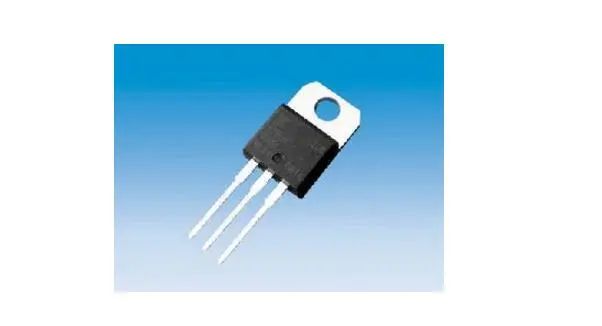
“Bidirectional Thyristor”: It is developed based on ordinary thyristors. It can replace two antiparallel thyristors and only requires one trigger circuit, making it a relatively ideal AC switching device. Its English name TRIAC means three-terminal bidirectional AC switch.
Characteristics and Applications of Bidirectional Thyristors
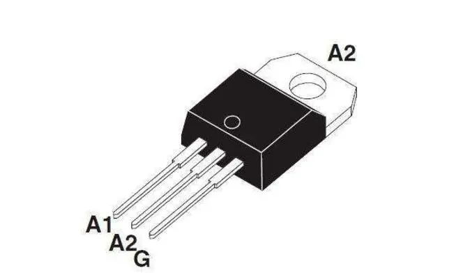
Bidirectional thyristors can be considered an integration of a pair of oppositely connected ordinary thyristors, and their working principle is the same as that of ordinary unidirectional thyristors. A bidirectional thyristor has two main electrodes T1 and T2, and one gate G. The gate allows the device to be triggered in both the positive and negative directions, so the bidirectional thyristor has symmetrical volt-ampere characteristics in the first and third quadrants. The gate of the bidirectional thyristor can be triggered by both positive and negative pulses, resulting in four triggering methods. To use bidirectional thyristors normally, it is necessary to quantitatively grasp their main parameters and select the appropriate bidirectional thyristor while taking corresponding measures to meet the parameter requirements.
· Selection of Voltage Rating: Generally, the smaller of VDRM (repetitive peak off-state voltage) and VRRM (repetitive peak reverse voltage) is marked as the rated voltage of the device. When selecting, the rated voltage should be 2 to 3 times the normal operating peak voltage to allow for permissible operating overvoltage margin.
· Determining Current: Since bidirectional thyristors are usually used in AC circuits, their rated current value is expressed in terms of effective value rather than average value. Because the overload capacity of thyristors is smaller than that of ordinary electromagnetic devices, the current value selected for thyristors in household appliances is generally 2 to 3 times the actual working current. At the same time, the peak current that the thyristor can withstand when subjected to the off-state repetitive peak voltage VDRM and the reverse repetitive peak voltage VRRM should be less than the specified IDRM and IRRM of the device.
· Selection of On-State (Peak) Voltage VTM: This is the instantaneous peak voltage drop across the thyristor when it conducts at the specified multiple of the rated current. To reduce thermal loss in the thyristor, it is advisable to choose a thyristor with a small VTM.
· Holding Current: IH is the minimum main current required to keep the thyristor in the on-state, which is related to the junction temperature; the higher the junction temperature, the smaller the IH.
· Resistance to Voltage Rise Rate: dv/dt refers to the slope of voltage rise in the off state, which is a key parameter to prevent false triggering. Exceeding this value may lead to false triggering of the thyristor. The manufacturing process of the thyristor determines that there will be parasitic capacitance between A2 and G.
Construction Principle of Bidirectional Thyristors
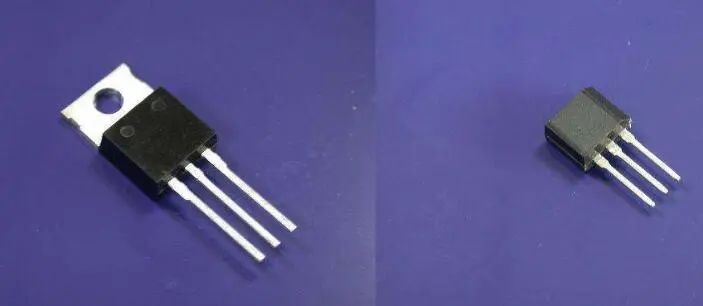
Although bidirectional thyristors can be seen as a combination of two ordinary thyristors in form, they are actually power integrated devices made up of 7 transistors and multiple resistors. Small power bidirectional thyristors generally use plastic packaging, some even come with heat sinks. Typical products include BCMlAM (1A/600V), BCM3AM (3A/600V), 2N6075 (4A/600V), MAC218-10 (8A/800V), etc. High power bidirectional thyristors mostly use RD91 type packaging.
Bidirectional thyristors belong to NPNPN five-layer devices, with three electrodes T1, T2, and G. Since this device can conduct in both directions, the two electrodes other than the gate G are collectively referred to as main terminals, represented as T1 and T2, without distinguishing between anode or cathode. Its characteristic is that when the voltage at the gate and T2 relative to T1 is positive, T2 is the anode and T1 is the cathode. Conversely, when the voltage at the gate and T2 relative to T1 is negative, T1 becomes the anode and T2 becomes the cathode. Due to the symmetrical characteristic curves in both directions, the bidirectional thyristor can conduct in either direction.
Design Tips for Bidirectional Thyristor Trigger Circuits
In electrical appliances, the selection of conductors and semiconductor components is crucial. The usage of various materials depends on our level of knowledge. Generally, for appliances with higher power and connected to strong electrical networks, we choose bidirectional thyristors. Bidirectional thyristors are a type of power semiconductor device, also known as bidirectional thyristors, which can serve as power driver devices in microcontroller control systems. Due to the absence of reverse voltage issues, the control circuit is simple, making them particularly suitable for use as AC non-contact switches. In today’s article, we will briefly introduce the design tips for trigger circuits of bidirectional thyristors.
Engineers are well aware that the anti-interference issue of the trigger circuit for bidirectional thyristors in electrical appliances is very important. Typically, the trigger signal from the microcontroller control system is loaded onto the control terminal of the thyristor through an optocoupler. To reduce the driving power and interference generated during the triggering of the thyristor, the triggering of bidirectional thyristors in AC circuits often uses zero-crossing triggering circuits. Zero-crossing triggering refers to the moment of conduction when the voltage is zero or near zero. Since zero-crossing triggering is used, the above circuit also requires a sine wave AC zero-crossing detection circuit.
1. Zero-Crossing Detection Circuit
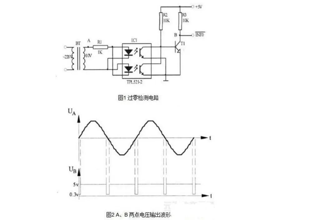
Figures 1 and 2 mainly introduce two scenarios for using bidirectional thyristors. It is clear that the purpose of Figure 1 is to improve efficiency, while Figure 2 shows the voltage output waveforms at points A and B in the zero-crossing detection circuit. In Figure 1, to improve efficiency, the triggering pulse must be synchronized with the AC voltage, requiring a triggering pulse to be output every half cycle of the AC voltage, with a pulse voltage greater than 4V and a pulse width greater than 20us. In the figure, BT is a transformer, TPL521-2 is an optocoupler, which serves to provide isolation. When the sine wave AC voltage approaches zero, both LEDs of the optocoupler are turned off, and the bias resistance potential at the base of transistor T1 turns it on, generating a negative pulse signal. The output of T1 connects to the external interrupt 0 input pin of the microcontroller 80C51 to trigger an interrupt. In the interrupt service routine, the timer accumulates the phase-shift time and then issues the synchronous trigger signal for the bidirectional thyristor. This type of circuit detection is the zero-crossing detection circuit.
2. Zero-Crossing Trigger Circuit
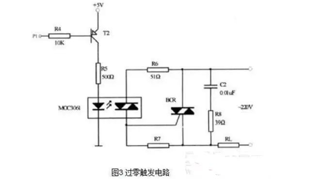
The diagram of the zero-crossing trigger circuit is shown in Figure 3. In the image, we can see the optocoupler bidirectional thyristor driver. The optocoupler bidirectional thyristor driver is a type of optocoupler used to drive the bidirectional thyristor BCR and provides isolation. R6 is the trigger current-limiting resistor, and R7 is the gate resistor for BCR to prevent false triggering and improve anti-interference capability. When the P1.0 pin of the microcontroller 80C51 outputs a negative pulse signal, T2 conducts, MOC3061 conducts, triggering BCR to turn on and connect the AC load. Additionally, if the bidirectional thyristor is connected to an inductive AC load, due to the power supply voltage leading the load current by a phase angle, when the load current is zero, the power supply voltage becomes reverse voltage. Coupled with the self-induced electromotive force of the inductive load, the voltage across the bidirectional thyristor far exceeds the power supply voltage. Although the bidirectional thyristor conducts in reverse, it can easily break down, so it is necessary to ensure that the bidirectional thyristor can withstand this reverse voltage. Generally, a parallel RC snubber circuit is connected across the bidirectional thyristor to achieve overvoltage protection. C2 and R8 in Figure 3 are the components of the RC snubber circuit.
3. Conclusion
The zero-crossing trigger circuit of bidirectional thyristors is mainly used in microcontroller control systems for AC load control circuits, which can control electric furnaces, AC motors, and other high-power AC devices. Practical experience has proven that it works safely and reliably. This article focuses on the zero-crossing detection and triggering circuits. As for software design, it is relatively simple. When the zero-crossing detection circuit detects a zero-crossing, it generates an interrupt request. In the interrupt service routine, a triggering pulse can be sent through the P1.0 pin of the microcontroller 80C51 to trigger the conduction of the bidirectional thyristor.


To help everyone learn better, Changxue Electronics has specially added a public account focused on microcontrollers and EDA, pushing relevant knowledge daily, hoping to assist your learning!