
Modern vehicles are increasingly equipped with electronic devices, necessitating good design practices to meet the requirements of major electromagnetic compatibility (EMC) standards. The rising levels of integration have also led automotive designers to urgently seek Application-Specific Integrated Circuits (ASICs) and Application-Specific Standard Products (ASSPs) that can replace multiple discrete components. This article discusses some of the EMC and integrated circuit (IC) challenges faced by automotive designers.

The electronic devices in modern vehicles are continuously evolving—engineers are developing increasingly complex solutions for comfort, safety, entertainment, powertrain, engine management, stability, and control applications. Moreover, advanced electronic systems are becoming more widely adopted. Thus, even the most ordinary vehicles today are equipped with electronic devices that were exclusive to high-end cars just a few years ago.

In the past, non-critical applications such as comfort and convenience drove the development of automotive electronics. Applications like power windows or central locking merely replaced existing mechanical systems. Recently, the scope of automotive electronics has expanded to support critical applications such as engine optimization, active and passive safety systems, and advanced infotainment systems, including global positioning systems.
We are currently entering the third phase of automotive electronics development. In this phase, electronic devices not only support critical functions but also control them—whether providing important driver information and controlling the engine, or detecting and preventing collisions, performing drive-by-wire and intelligent climate control. As you might imagine, these applications require cost-effective, easy-to-install, and increasingly intelligent and stable electronic solutions.
Speed and cost factors have facilitated the emergence of “generic” embedded hardware electronic platforms. These platforms can provide basic or common hardware functions and can be customized with dedicated application software to meet the needs of different models within the same vehicle series, and even for different automotive manufacturers. System-on-Chip (SoC) semiconductor solutions integrate multiple functions into a single integrated circuit, reducing the number of components and minimizing space requirements while ensuring long-term reliability, which is crucial for the successful development of generic embedded electronic platforms.
Electromagnetic Compatibility
As the number of electronic devices in vehicles increases and complex electronic modules are applied widely throughout the vehicle, electromagnetic compatibility issues are becoming an increasingly significant design challenge for engineers. Three main problems are:
(a) How to minimize electromagnetic sensitivity so that electronic devices are not affected by electromagnetic emissions from other electronic systems such as mobile phones, GPS, or infotainment devices.
(b) How to protect electronic devices from adverse automotive environments, including transients in the power supply system and interference during the switching of large loads or inductive loads like lights and starter motors.
(c) How to minimize electromagnetic emissions that may affect other automotive electronic circuits.
Moreover, as system voltage increases, the number of vehicle electronic devices rises, and more high-frequency electronic devices contribute to an increase in frequency, these issues are becoming increasingly challenging. Additionally, many electronic modules now interface with low-cost sensors that have poor linearity and large offset, which rely on small signals; electromagnetic interference can be catastrophic for their normal operation.
Compatibility Testing, Pre-Compatibility Testing, and Standards
These issues mean that automotive electromagnetic compatibility testing has become a fundamental aspect of automotive design. Compatibility testing has been standardized among automotive manufacturers, their suppliers, and various legislative bodies. The later electromagnetic compatibility issues are discovered, the harder it becomes to identify their root causes, and the solutions may become more limited and costly. Therefore, considering electromagnetic compatibility issues at all stages of the process is a fundamental practice—from integrated circuit design and printed circuit board layout to module installation and final vehicle layout design. To simplify this process, pre-compatibility testing that considers electromagnetic compatibility issues at the module and integrated circuit stage has been standardized.
Designing Integrated Circuits and Modules that Meet EMC Requirements
For integrated circuits, there are three main electromagnetic compatibility standards: Electromagnetic Emission Standards – IEC 61967: Measurement of radiated and conducted electromagnetic emissions in the range of 150 kHz to 1 GHz; Electromagnetic Sensitivity Standards – IEC 62132: Measurement of electromagnetic immunity in the range of 150 kHz to 1 GHz; Transient Standards – ISO 7637: Electrical disturbances caused by conduction and coupling in road vehicles.
So, how can system designers ensure that their SoCs and final modules meet these standards? Traditional SPICE models are of no use here, as electromagnetic fields are incompatible with the SPICE simulation environment. Because the size of chips and entire components is much smaller than the wavelength of electromagnetic signals (30 cm at 1 GHz, far greater than the size of integrated circuits), it is sufficient to establish models using only the electric field at the integrated circuit level. It is noteworthy that radiated emissions and sensitivity are not primary concerns for integrated circuits; the main issues are conducted emissions and sensitivity to effective antennas on printed circuit boards and wiring harnesses.
Several techniques are employed to ensure compliance with electromagnetic compatibility requirements; we will examine the issues of electromagnetic emissions and electromagnetic sensitivity one by one.
Electromagnetic Emissions
Electromagnetic emissions are produced by high-frequency currents in external loops acting as antennas. These high-frequency currents originate from the switching of core digital logic such as digital signal processing and clock drivers (synchronous logic generates large, sharp current peaks with many high-frequency components), the operation of analog circuits, switching digital input/output pins, and high-power output drivers providing high current peaks for printed circuit boards and wiring harnesses. To minimize these factors, designers should use low-power circuits whenever possible, which may include reducing or using adaptive power supply voltages or distributing clock signals across the entire frequency domain. Reducing the number of switching elements in a clock cycle by shutting down unused parts of the digital system can also help. Additionally, controlling the rise/fall times of clock and driver signals to slow down switching edges and provide soft-switching characteristics also helps reduce electromagnetic emissions. Lastly, designers should carefully consider external and chip layout methods. For example, using differential output signals with twisted pairs generates less electromagnetic emissions and is less sensitive to electromagnetic emissions. Ensuring power and ground are close to each other and using efficient power decoupling are also simple methods to reduce electromagnetic emissions.
Electromagnetic Sensitivity
Rectification/oscillation, parasitic devices, current, and power consumption are the three most severe interference effects for low electromagnetic sensitivity. High-frequency electromagnetic power is absorbed by integrated circuits, which can cause some interference, including outputting high-frequency high voltage to high-impedance nodes and high-frequency large current to low-impedance nodes.
One important method to minimize the impact of electromagnetic sensitivity is to make the circuit symmetric, thus avoiding rectification. This can be achieved by using differential circuit topologies and layouts. Even in applications (such as sensor usage) that require small signals, topologies that can handle larger common-mode signals can help the system remain linear in the presence of large electromagnetic signals. Another commonly used method is to limit the frequency input range of sensitive devices through filtering, especially using on-chip filters. Designing with a high common-mode rejection ratio (CMRR) and power supply rejection ratio (PSRR) can also help prevent rectification, and reducing internal node impedance and placing all sensitive nodes on the chip can achieve this effect. Finally, to avoid or control parasitic devices and currents, it is crucial to use protective devices to limit exceeding electromagnetic sensitivity suppression levels. This helps to avoid rectification and keep signal levels symmetrical, and it is also important to minimize substrate currents and dissipate currents at critical locations.
Latest Semiconductor Technologies
Many designers are leveraging mixed-signal semiconductor technologies to provide the system-on-chip solutions needed for today’s automotive applications. The latest high-voltage mixed-signal technology is particularly suitable for designs requiring high voltage outputs—such as driving motors or starter relays—combined with analog signal conditioning functions and complex digital processing.
The I2T and I3T series developed by AMIS Semiconductor exemplify the latest high-voltage mixed-signal application-specific integrated circuit technology. The I3T80, based on a 0.35-micron CMOS process, can handle a maximum voltage of 80 volts, allowing complex digital circuits, embedded microprocessors, memory, peripherals, high-voltage functions, and various interfaces to be integrated into a single integrated circuit.
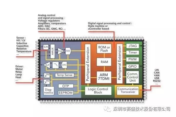
Figure 1: Several functions integrated into a single chip manufactured using the I3T80 process
Figure 1 illustrates several functions integrated into a single chip manufactured using the I3T80 process, including sensor analog interfaces (one of the most common requirements in automotive applications), high-voltage drivers for motors and transmissions, and digital processing circuits using embedded 16/32-bit ARM(tm) processor cores. For low-power processing needs, an 8-bit embedded R8051 processor is also provided. As shown, other ‘standard’ IP modules offered by AMIS include timers, pulse-width modulation (PWM) functions, JTAG for simplifying device testing, and communication transceivers including CAN and LIN bus communication options. It should also be noted that the I3T technology includes built-in protection features to prevent damage to the application-specific integrated circuits due to over-voltage or battery misconnection.
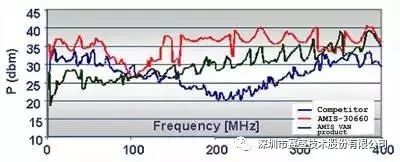
Figure 2: Comparison of electromagnetic immunity performance of AMIS-30660 with other competing products
AMIS has used this mixed-signal technology and many reasonable design methods for electromagnetic compatibility described in this article to develop various application-specific standard products (ASSPs) for the automotive industry, including AMIS-41682 standard speed, AMIS-42665, and AMIS-30660 high-speed CAN transceivers. These devices provide interfaces between CAN controllers and physical buses, simplifying designs in 12V and 24V automotive applications and industrial applications requiring CAN communication at a maximum rate of 1 Mbps, while reducing the number of components. For example, the AMIS-30660 fully complies with ISO 11898-2 standards, providing differential transmit signal capability for the CAN bus via the transmit and receive pins of the CAN controller. The integrated circuit offers designers a choice of 3.3V or 5V logic level interfaces, ensuring compatibility with existing applications and the latest low-voltage designs. Well-matched output signals minimize electromagnetic emissions, eliminating the need for common-mode chokes; the receiver input’s large common-mode voltage range (±35V) ensures high electromagnetic sensitivity (EMS). Figure 2 shows a comparison of the electromagnetic immunity performance of AMIS-30660 with other competing products.
About Saiseng Technology:
Founded in 2005 and listed in 2016, stock abbreviation: Saiseng Technology, stock code: 839017. Focused on electromagnetic compatibility (EMC) and other engineering technologies, providing enterprises with product EMC issue rectification, product EMC design, EMC technology training, and system construction consulting services.
About Saiseng WeChat Official Account:
A professional platform for electromagnetic compatibility technical information, providing EMC technical knowledge, case analysis, industry information, etc. Helping engineers improve their EMC technical level! Please follow us!

【Disclaimer: Some materials are sourced from the internet, and the purpose of reproduction is to transmit more information and share, which does not imply endorsement of their views or verification of their authenticity, nor does it constitute other advice, and is only provided as a communication platform. We do not take responsibility for copyright issues. If there is any infringement, please contact us for timely modification or deletion.】