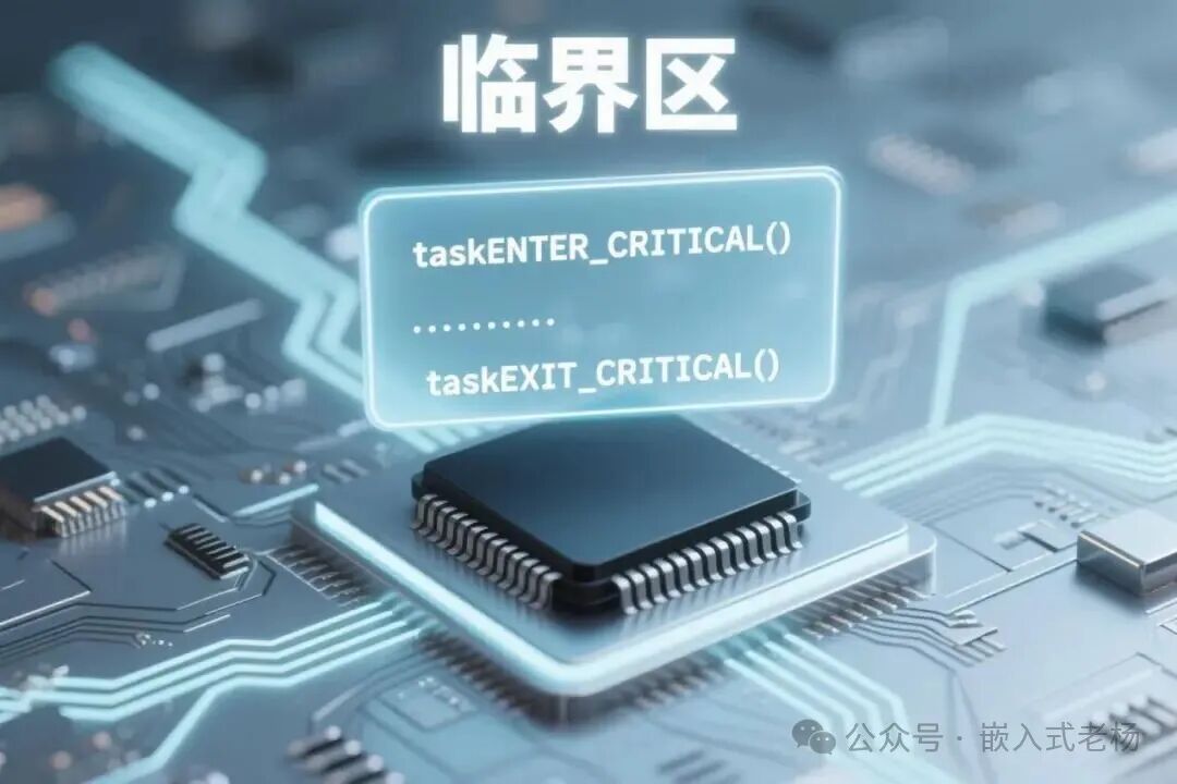
“ In the ESP32 multi-tasking system based on FreeRTOS, sharing resources among multiple tasks or interrupts can easily lead to race conditions. To address this issue, critical sections are essential. The following will elaborate on their function and principles, detail the relevant APIs in the IDF version, and provide code examples in scenarios such as multi-tasking shared variables and tasks sharing UART buffers, along with usage precautions.”
01
—
Function of Critical Sections
In multi-tasking systems based on FreeRTOS, such as the ESP32, multiple tasks or interrupts may simultaneously access shared resources (e.g., global variables, hardware registers, peripheral buffers, etc.). Without protection, this can lead to a “race condition”—for example, two tasks modifying the same variable simultaneously, resulting in data inconsistency.
The core function of a critical section is to ensure that shared resources can only be accessed by one task or interrupt at a time through a mutual exclusion mechanism, guaranteeing atomic execution of code segments and preventing data errors or system anomalies.
02
—
Principle of Critical Sections (Based on ESP32 IDF)
The FreeRTOS critical section in ESP32 is implemented by controlling the interrupt enable state:
When entering a critical section, the system saves the current CPU’s interrupt mask status (uxSavedInterruptStatus) and then disables interrupts (only masking interrupts with priority values ≤configMAX_SYSCALL_INTERRUPT_PRIORITY; higher priority interrupts can still respond to ensure real-time performance).
When exiting the critical section, the previously saved interrupt state is restored, allowing the system to resume normal scheduling and interrupt response.
In ESP32 IDF, the implementation of critical sections is consistent with standard FreeRTOS but must be combined with the interrupt management mechanism of ESP-IDF (e.g., ESP_INTR_FLAG_IRAM and other interrupt flags).
03
—
Critical Section Related API Interfaces
The FreeRTOS critical section APIs used in ESP-IDF are fully compatible with standard FreeRTOS and are divided into task-level and interrupt-level categories:

04
—
Application Scenarios and Example Code
Scenario 1: Multi-tasking Shared Global Variable (Task-Level Critical Section)
Problem:
Two tasks simultaneously incrementing a global counter g_counter may lead to counting errors due to task switching.
Solution:
Wrap the counting operation with taskENTER_CRITICAL() and taskEXIT_CRITICAL() to ensure atomicity.
#include <stdio.h>
#include "freertos/FreeRTOS.h"
#include "freertos/task.h"
// Shared resource: global counter
static uint32_t g_counter = 0;
// Task 1: Increment counter
static void vTask1(void *pvParameters) {
    while (1) {
        // Enter critical section: disable interrupts to prevent task switching
        taskENTER_CRITICAL();
        // Critical section: operate on shared resource
        g_counter++;
        printf("Task1: Counter = %u\n", g_counter);
        // Exit critical section: restore interrupts
        taskEXIT_CRITICAL();
        vTaskDelay(pdMS_TO_TICKS(100)); // Delay to yield CPU
    }
}
// Task 2: Increment counter
static void vTask2(void *pvParameters) {
    while (1) {
        taskENTER_CRITICAL();
        g_counter++;
        printf("Task2: Counter = %u\n", g_counter);
        taskEXIT_CRITICAL();
        vTaskDelay(pdMS_TO_TICKS(150));
    }
}
void app_main(void) {
    // Create two tasks (ESP32 supports multi-core, here default runs on APP_CPU)
    xTaskCreatePinnedToCore(vTask1, "Task1", 2048, NULL, 1, NULL, 1);
    xTaskCreatePinnedToCore(vTask2, "Task2", 2048, NULL, 1, NULL, 1);
}
Note:
In the dual-core environment of ESP32, critical sections can only ensure mutual exclusion of tasks on a single core. If cross-core protection is needed, it must be combined with spin locks (vPortCPUAcquireMutex()), but critical sections can still solve race conditions within a single core.
Critical sections ensure that the “read-modify-write” three-step operation of g_counter++ is not interrupted by task switching, resulting in accurate counting.
Scenario 2: Task and Interrupt Sharing UART Buffer (Interrupt-Level Critical Section)
Problem:
The UART receive interrupt (ISR) writes data to the buffer, while the application task reads data from the buffer. If the read and write are not synchronized, it may lead to data corruption.
Solution:
Protect the task reading with taskENTER_CRITICAL();
Use taskENTER_CRITICAL_FROM_ISR() and taskEXIT_CRITICAL_FROM_ISR() to protect the ISR writing.
#include <stdio.h>
#include <string.h>
#include "freertos/FreeRTOS.h"
#include "freertos/task.h"
#include "driver/uart.h"
#include "esp_log.h"
// Shared resource: UART receive buffer (circular buffer)
#define BUF_SIZE 128
static uint8_t g_uart_buf[BUF_SIZE];
static uint16_t g_wr_idx = 0; // Write index (modified by ISR)
static uint16_t g_rd_idx = 0; // Read index (modified by task)
static const char *TAG = "UART_DEMO";
// UART interrupt service routine
static void IRAM_ATTR uart_isr_handler(void *arg) {
    uint32_t uxSavedStatus;
    uart_port_t uart_num = (uart_port_t)arg;
    uint8_t data;
    // Read received data (loop through all waiting data)
    while (uart_isr_get_hw_flag(uart_num, UART_RXFIFO_FULL_INT_CLR)) {
        uart_read_bytes(uart_num, &data, 1, 0);
        // Enter interrupt critical section: save interrupt status
        uxSavedStatus = taskENTER_CRITICAL_FROM_ISR();
        // Critical section: write to circular buffer (check if not full)
        uint16_t next_wr = (g_wr_idx + 1) % BUF_SIZE;
        if (next_wr != g_rd_idx) {
            g_uart_buf[g_wr_idx] = data;
            g_wr_idx = next_wr;
        } else {
            ESP_LOGE(TAG, "Buffer full! Data lost: 0x%02X", data);
        }
        // Exit interrupt critical section: restore interrupt status
        taskEXIT_CRITICAL_FROM_ISR(uxSavedStatus);
    }
    // Clear interrupt flag
    uart_clear_intr_status(uart_num, UART_RXFIFO_FULL_INT_CLR);
}
// Task: Read from buffer and print data
static void vUARTReadTask(void *pvParameters) {
    while (1) {
        taskENTER_CRITICAL(); // Enter task critical section
        // Critical section: read from buffer (check if not empty)
        if (g_rd_idx != g_wr_idx) {
            uint8_t data = g_uart_buf[g_rd_idx];
            g_rd_idx = (g_rd_idx + 1) % BUF_SIZE;
            printf("Received: %c (0x%02X)\n", data, data);
        }
        taskEXIT_CRITICAL(); // Exit task critical section
        vTaskDelay(pdMS_TO_TICKS(50));
    }
}
// Initialize UART
static void uart_init(void) {
    uart_config_t uart_config = {
        .baud_rate = 115200,
        .data_bits = UART_DATA_8_BITS,
        .parity = UART_PARITY_DISABLE,
        .stop_bits = UART_STOP_BITS_1,
        .flow_ctrl = UART_HW_FLOWCTRL_DISABLE,
    };
    uart_param_config(UART_NUM_0, &uart_config);
    uart_set_pin(UART_NUM_0, UART_PIN_NO_CHANGE, UART_PIN_NO_CHANGE, UART_PIN_NO_CHANGE, UART_PIN_NO_CHANGE);
    uart_driver_install(UART_NUM_0, BUF_SIZE * 2, 0, 0, NULL, 0);
    // Register interrupt handler (ESP-IDF specific: must specify interrupt priority and IRAM flag)
    uart_isr_register(UART_NUM_0, uart_isr_handler, (void *)UART_NUM_0, ESP_INTR_FLAG_IRAM | ESP_INTR_FLAG_LEVEL1, NULL);
    uart_enable_intr_mask(UART_NUM_0, UART_RXFIFO_FULL_INT_ENA); // Enable receive interrupt
}
void app_main(void) {
    uart_init();
    xTaskCreatePinnedToCore(vUARTReadTask, "UARTReadTask", 4096, NULL, 2, NULL, 0);
}
Note:
In ESP-IDF, interrupt handler functions must be marked with IRAM_ATTR to ensure the code is loaded into IRAM, avoiding cache issues.
The ESP_INTR_FLAG_LEVEL1 specified in uart_isr_register() sets the interrupt priority (must be ≤configMAX_SYSCALL_INTERRUPT_PRIORITY; otherwise, the critical section cannot mask this interrupt).
Critical sections protect the modification of buffer indices, preventing data overwriting or loss due to read-write conflicts.
Scenario 3: Atomic Operations for SPI Hardware Configuration (Short Critical Section)
Problem:
Configuring the SPI controller of the ESP32 requires writing to multiple registers consecutively, and if interrupted, it may lead to SPI timing errors.
Solution:
Wrap the entire configuration process in a critical section to ensure the operation completes continuously.
#include <stdio.h>
#include "freertos/FreeRTOS.h"
#include "freertos/task.h"
#include "driver/spi_master.h"
#include "esp_log.h"
static const char *TAG = "SPI_DEMO";
static spi_device_handle_t spi_dev;
// Task: Configure SPI and send data
static void vSPITask(void *pvParameters) {
    while (1) {
        // Wait for trigger signal (e.g., external event)
        // ...
        taskENTER_CRITICAL(); // Enter critical section, ensure configuration is not interrupted
        // Critical section: consecutive configuration of SPI registers (example)
        spi_bus_config_t buscfg = {
            .miso_io_num = 19,
            .mosi_io_num = 23,
            .sclk_io_num = 18,
            .quadwp_io_num = -1,
            .quadhd_io_num = -1,
            .max_transfer_sz = 4096,
        };
        spi_device_interface_config_t devcfg = {
            .clock_speed_hz = 10 * 1000 * 1000, // 10MHz
            .mode = 0,
            .spics_io_num = 5,
            .queue_size = 1,
        };
        // Initialize SPI bus and device (should only initialize once in practice, here for example)
        spi_bus_initialize(SPI2_HOST, &buscfg, SPI_DMA_CH_AUTO);
        spi_bus_add_device(SPI2_HOST, &devcfg, &spi_dev);
        taskEXIT_CRITICAL(); // Exit critical section
        // Send data (non-critical section operation)
        uint8_t data = 0xAA;
        spi_transaction_t t = {
            .length = 8,
            .tx_buffer = &data,
        };
        spi_device_transmit(spi_dev, &t);
        ESP_LOGI(TAG, "SPI data sent: 0x%02X", data);
        vTaskDelay(pdMS_TO_TICKS(1000));
    }
}
void app_main(void) {
    xTaskCreatePinnedToCore(vSPITask, "SPITask", 4096, NULL, 3, NULL, 1);
}
Note:
Hardware configuration code typically executes quickly and is suitable for protection with critical sections. The SPI configuration of the ESP32 involves multiple register operations that must ensure continuity.
Critical sections should be as short as possible; here, only the configuration process is wrapped, while data sending operations are executed outside the critical section to reduce interrupt blocking time.
05
—
Usage Precautions
Interrupt Priority:
The interrupt priority of the ESP32 (0-7) must be ≤configMAX_SYSCALL_INTERRUPT_PRIORITY (default 5); otherwise, the critical section cannot mask this interrupt, which may lead to race conditions.
IRAM Restrictions:
The critical section code in interrupt handler functions must be placed in IRAM (marked with IRAM_ATTR) to avoid delays caused by Flash caching.
Dual-Core Synchronization:
If cross-core (PRO_CPU and APP_CPU) protection of shared resources is needed, it must be combined with vPortCPUAcquireMutex() and vPortCPUReleaseMutex(); a critical section alone only acts on the current core.
Avoid Nesting:
Although FreeRTOS supports nested critical sections (internally implemented with a counter), the interrupt response time of the ESP32 is sensitive, and nesting may increase latency.
Previous Articles:
Low Power Mode for GPIO
Firmware Burning Methods for Embedded Systems
Principles of FreeRTOS Task Priority Configuration
Introduction to FreeRTOS Tasks
Types, Working Principles, and Applications of Diodes
Low Power Modes for MCUs
Wi-Fi 7 is here! 5 times faster than Wi-Fi 6, your network is about to take off!
Recommended book for beginners in electronic design (includes electronic version)
ADC Sampling and Filtering Algorithms for Microcontrollers