Introduction: The rapid development of automotive technology and the popularization of fuel-injected vehicles have brought challenges to many automotive repair professionals. To become an excellent automotive technician and increase income, understanding automotive circuit knowledge is essential.
Many automotive repair friends have expressed a desire to learn about circuits. After reading this article, you should have a general understanding of the basic knowledge of circuits. Good things should be shared with everyone~
This article is quite comprehensive, so it may be a bit long. For those who are busy and cannot finish it at once, feel free to forward or bookmark it to read later~
Classification of Automotive Circuit Diagrams
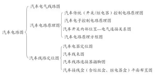
Electrical Wiring Diagram
Circuit Schematic Diagram
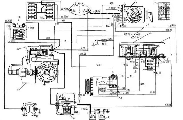
The circuit schematic diagram focuses on expressing the working principles of various electrical systems’ circuits. It can be a complete vehicle circuit diagram or schematic diagrams of individual systems.
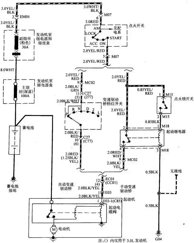
1. Traditional (Switch/Relay) Control Circuit Schematic Diagram
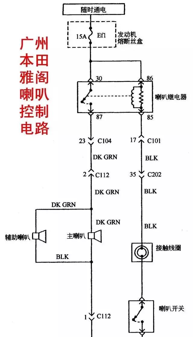
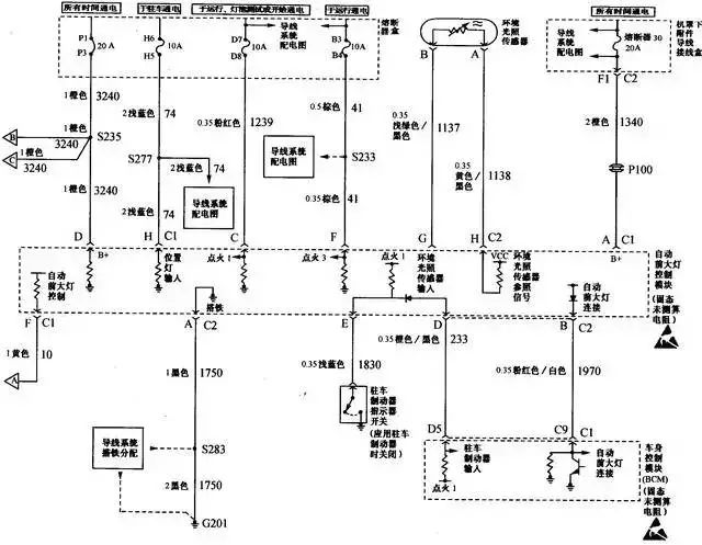
2. Automotive Electronic Control Circuit Schematic Diagram
The following diagram is the control circuit schematic for the front headlights of a Buick sedan.
3. Internal Position of Automotive Switches – Electrical Connection Relationship Diagram
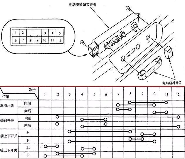
The following diagram shows the electrical connection relationship of the power seat switch for the Honda Accord.
4. Automotive Circuit Principle Block Diagram
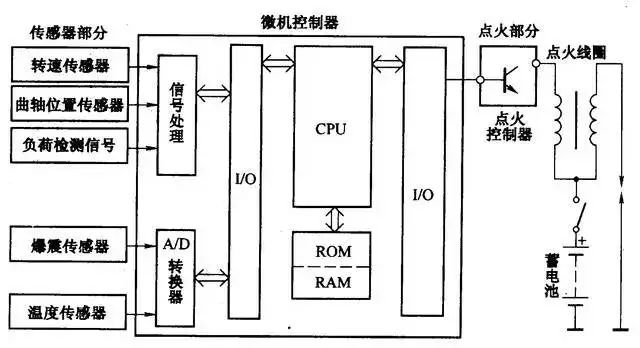
The block diagram divides a complete circuit into several parts, each represented by a block. Each block is further described by text or symbols, and the blocks are connected by lines to show their interrelationships without detailing the components and their specific connections.
Circuit Location Diagram
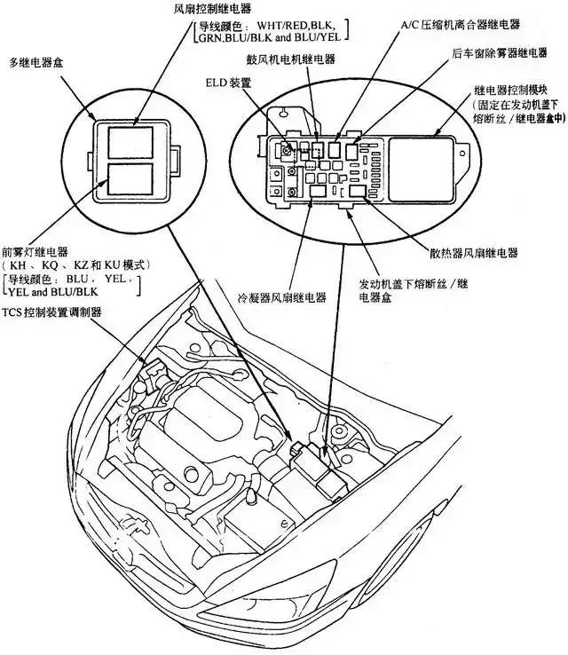
The circuit location diagram indicates the specific positions of electrical devices and wires. It is generally presented in the form of a three-dimensional drawing or a real photo, providing a strong sense of three-dimensionality and clearly reflecting the actual positions of electrical devices in the vehicle, making it highly practical. The location diagram can also be subdivided into automotive electrical location diagrams, automotive wiring harness diagrams, automotive circuit connector pin diagrams, and automotive junction box (including fuse box, relay box) layout diagrams.
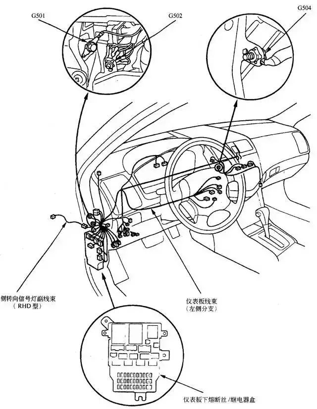
1. Automotive Electrical Location Diagram
Identifies the distribution positions of electrical components, connectors, junction boxes, grounding points, hinge points, and diagnostic sockets. The following diagram shows the grounding point location for the Honda Accord.
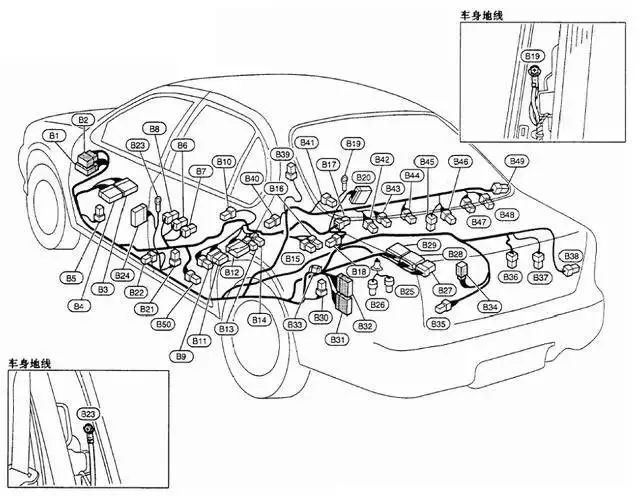
2. Automotive Wiring Harness Diagram
Identifies the connection points of the wiring harness with each electrical device, marking the terminals, wire ends, connector shapes, and positions.
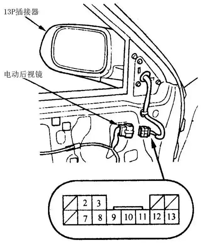
3. Automotive Circuit Connector Pin Diagram
Identifies the connection positions of wires inside the connector. The following diagram shows the connector pin diagram for the electric rearview mirror.
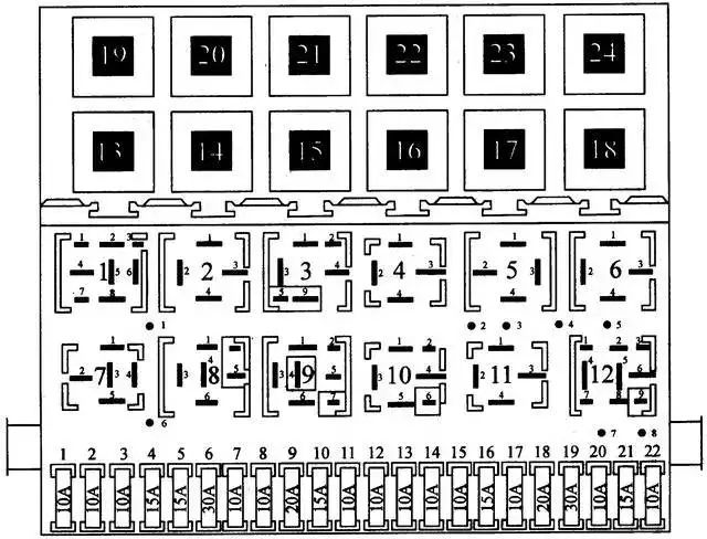
4. Automotive Junction Box (including fuse box, relay box) layout diagram
Identifies the specific installation positions for fuses, relays, etc.
Characteristics of Circuit Schematics for Various Vehicle Models
Horizontal Coordinate Circuit Diagram
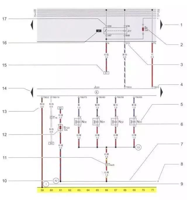
This type of circuit diagram marks the position of each wire in the diagram at the bottom using numbered coordinates, with wires arranged in parallel, each aligned with a number on the bottom frame line. Generally, lateral crossings of wires are not allowed, and lateral connections are represented by break marks indicating the position of the other segment of wire connected to it. Mainly used for German Volkswagen models.
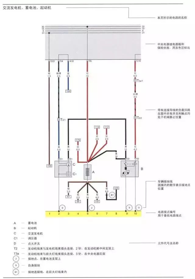
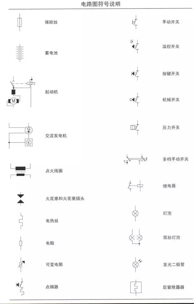
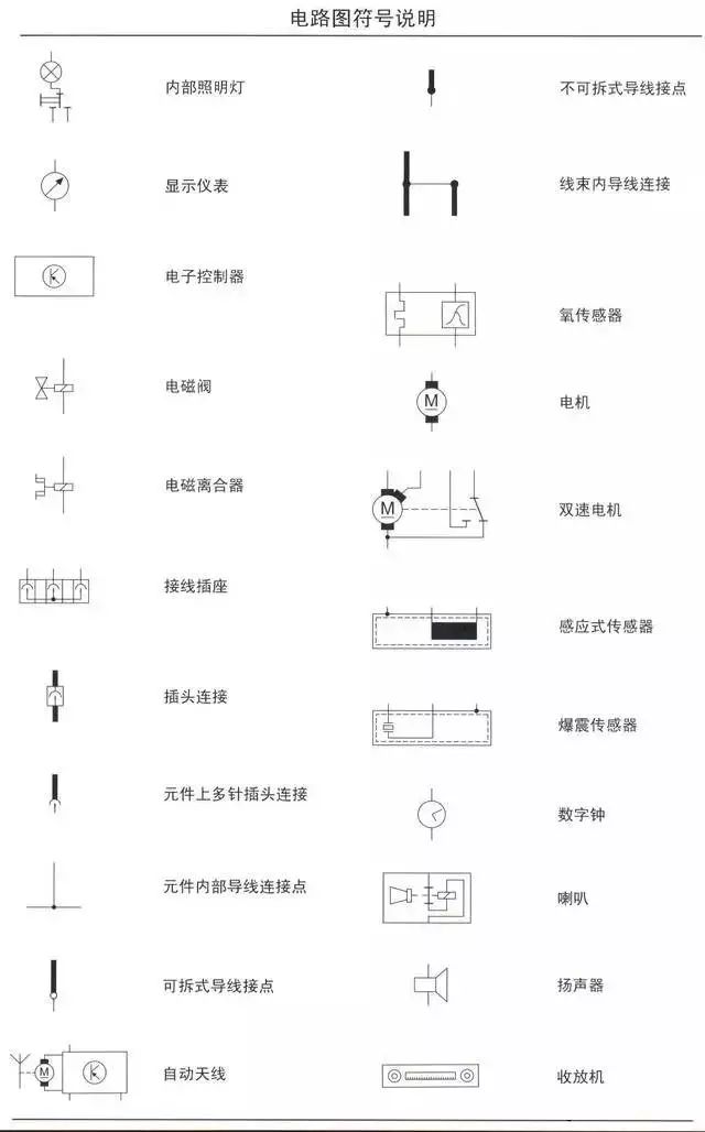
The circuit schematic explanation is as follows:
1—Triangle arrow indicates the connection to the next page of the circuit diagram.
2—Fuse code, where S5 indicates that this fuse is located in position 5 of the fuse box, 10 amps.
3—Relay board plug connection code, indicating the position of multi-pin or single-pin plug connections and wires, such as D13 indicating multi-pin plug connection, D position contact 13.
4—Terminal code, indicating the number of terminals on electrical components/multi-pin plug connection contact numbers.
5—Component code, which can be referenced at the bottom of the circuit diagram for the component name.
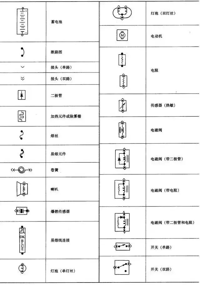
6—Component symbol, which can be referenced in the circuit diagram symbol explanation.
7—Internal wiring (thin solid line), indicating that this wiring is not set as a wire, but represents the internal circuit of components or wire harnesses.
8—Indicates the direction of internal wiring, with letters indicating that internal wiring connects to the same letter marked internal wiring on the next page of the circuit diagram.
9—Ground point code, which can be referenced at the bottom of the circuit diagram for the location of that code’s ground point in the vehicle.
10—The code for the wires within the harness, which can be referenced at the bottom of the circuit diagram for the location of that non-detachable connection within which wire harness.
11—Plug connection, for example, T8a/6 indicates pin 6 of the 8-pin a plug.
12—Additional fuse symbol, for example, S123 indicates a 10-amp fuse in position 23 on the central electrical additional relay board.
13—Wire color and cross-sectional area (unit: square millimeters).
14—Triangle arrow indicating that the component connects to the previous page of the circuit diagram.
15—Indicates the direction of the wire, with numbers in the box indicating which connection point number the wire connects to.
16—Relay position number, indicating the relay position number on the relay board.
17—Relay board’s relay or controller wiring code, indicating the various contacts of the relay’s multi-pin plug. For example, 2/30 indicates: 2=contact 2 of the relay board’s position 2 socket, 30=contact 30 on the relay/controller.
Horizontal and Vertical Coordinate Circuit Diagram
This type of circuit diagram uses horizontal and vertical coordinates to determine the position of electrical devices in the circuit diagram, such as Mercedes-Benz using numbers for horizontal coordinates and letters for vertical coordinates to locate the circuit.
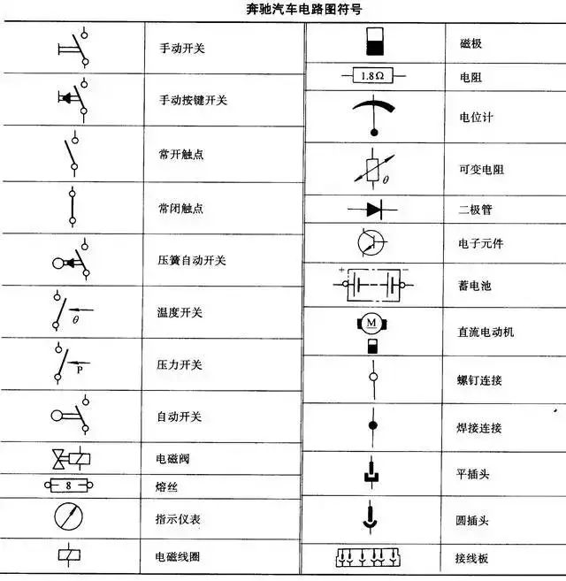
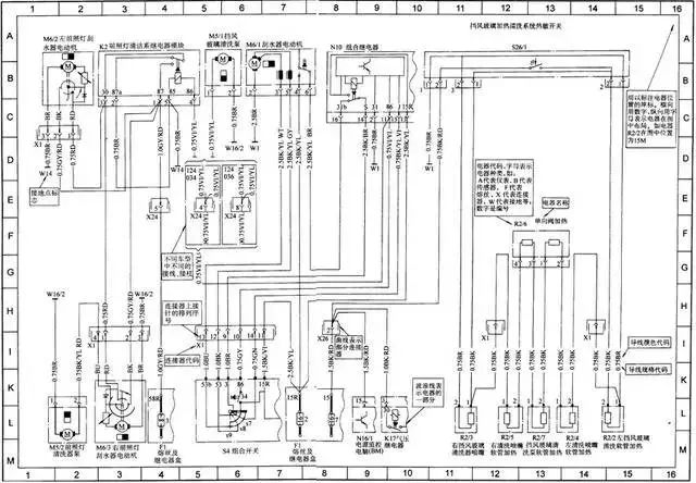
Module Circuit Diagram without Coordinates
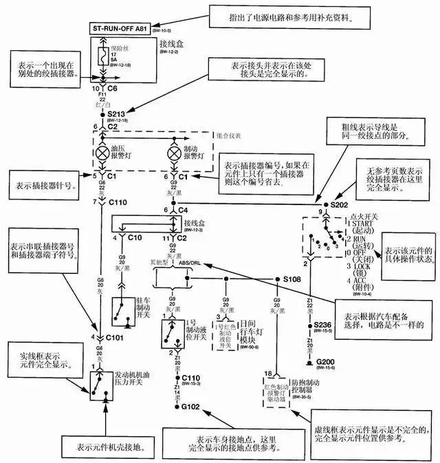
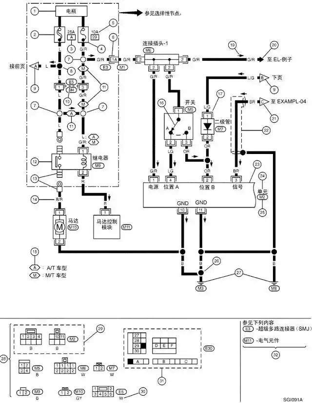
The module circuit diagram without coordinates is not a characteristic; it is categorized here mainly for comparison with other forms of circuit diagrams. Currently, many automotive manufacturers use this method, such as General Motors Buick, Honda, Dongfeng Citroen, Fukang, Toyota, Ford, BMW, Mitsubishi, etc. However, each company’s specific circuit expression methods and graphic symbols differ, so it is necessary to refer to related circuit diagrams and graphic symbol lists when reading the diagrams.
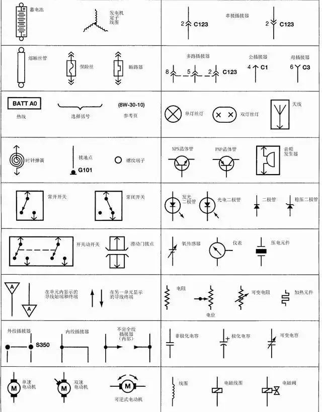
Example 1: Beijing Cherokee (Daimler-Chrysler) Circuit Schematic Diagram
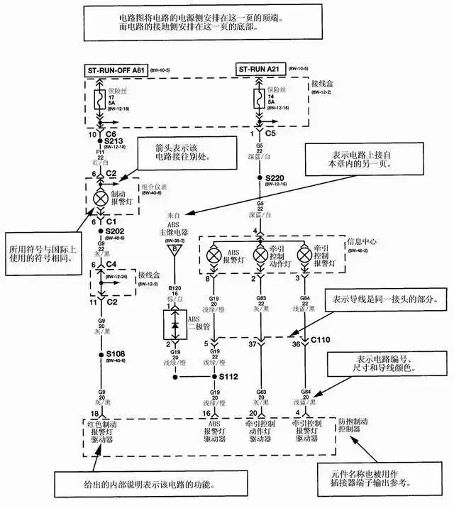
Example 2: Nissan Automotive Circuit Schematic Diagram
Mitchell Circuit Diagrams
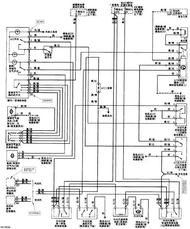
Mitchell is a well-known automotive repair data supplier in North America, with its automotive book products accounting for 70% of the North American market and database CD products accounting for 50%. In 1997, the China Vehicle Inspection Center signed a database transfer licensing contract with Mitchell and established a fully Chinese CVIC automotive repair database. Mitchell’s circuit diagrams have become important materials for automotive repair in China.
Characteristics of Mitchell Circuit Diagrams:
1. Mitchell circuit diagrams include those from major automotive manufacturers in the USA, Europe, and Asia, drawn according to a unified format and electrical symbols for ease of use.
2. In the electrical control system circuit diagrams, the electrical control unit is at the center, with its pins arranged in order according to codes, and the components around it generally have the power section at the top of the diagram and the grounding section at the bottom.
3. Electrical components are generally around, with wires in the middle.
General Principles for Reading Automotive Circuit Diagrams
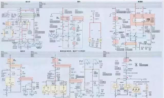
1. Carefully read the diagram notes.
The notes explain the names and digital codes of all electrical devices in the vehicle, and by reading the notes, you can initially understand which electrical devices are equipped in the vehicle. Then, find the corresponding electrical device in the circuit diagram using its digital code and further identify the interconnections and control relationships.
2. Memorize the electrical graphic symbols.
Automotive circuit diagrams use electrical graphic symbols to represent their composition and working principles. Therefore, it is essential to remember the meanings of the circuit graphic symbols to understand the circuit schematic diagrams.
3. Familiarize yourself with circuit marking symbols.
To facilitate drawing and reading automotive electrical circuit diagrams, some electrical devices or their terminals are assigned different marking codes.
4. Remember the characteristics of automotive circuits.
The characteristics of automotive circuits are:
1. Single-line system
2. Negative ground
3. Electrical devices are connected in parallel
5. Understand the loop principle.
Any complete circuit consists of a power source, fuses, switches, control devices, electrical devices, and wires. The current must flow from the positive side of the power source, through the fuse, switch, control device, and wires to the electrical device, and then return through the wires (or ground) to the negative side of the power source to form a loop. Therefore, when reading the circuit, there are three thought processes:
Thought process one: Follow the direction of current flow from the positive side of the power source, tracing to the electrical device, switches, control devices, etc., back to the negative side of the power source.
Thought process two: Start from the negative side (ground) of the power source, tracing through the electrical device, switches, control devices, etc., back to the positive side of the power source.
Thought process three: Start from the electrical device, sequentially find its control switches, connections, and control units, reaching the positive side and ground (or negative side) of the power source.
In practical applications, you can choose different thought processes based on the specific circuit, but one point to note is that with the widespread application of electronic control technology in vehicles, most electrical devices’ circuits simultaneously have main and control loops, so reading diagrams must consider both loops.
6. Browse the entire diagram and divide the various unit systems.
To understand automotive circuit diagrams, you must first grasp the basic functions and electrical characteristics of the various electrical components that make up the circuit. Based on a general understanding of the basic principles of the entire diagram, divide the circuit of each unit system, making it easier to grasp the main functions and characteristics of each part.
When delineating each system, it is essential to adhere to the loop principle, ensuring that no components within the various systems are omitted, and no components from other systems are included. The general rule is:
Each electrical system only shares the power source and main switch; any other system should be a complete independent electrical loop, including power source, switches (fuses), electrical devices (or electronic circuits), wires, etc. From the positive side of the power source through wires, switches, fuses to the electrical device, grounding, and finally returning to the negative side of the power source.
7. Familiarize yourself with the internal connections and relationships between various local circuits.
From the perspective of the entire vehicle circuit, aside from the shared power circuit, other unit circuits are relatively independent, but they also have internal connections (such as signal sharing). Therefore, when reading diagrams, it is essential to be familiar with the composition, characteristics, working processes, and current paths of each local circuit, as well as the connections and interrelationships between them. This is necessary for quickly locating faults and troubleshooting.
8. Understand the role of various switches in the circuit.
For multi-layer multi-position terminal switches, analyze the functions of each layer and position by layer and terminal. Some electrical devices are controlled by two or more single-position switches (or relays), while others are controlled by two or more multi-position switches, making their working states relatively complex. When switches have many terminals, first grasp one or two terminals coming from the power source, then analyze the connections to the other terminals to determine the control relationships.
For combination switches, the actual wiring is together, but in the circuit diagram, they are drawn in their respective local circuits according to their functions. When encountering such situations, it is necessary to study them carefully.
9. Analyze the initial and working states of switches and relays comprehensively. In circuit diagrams, various switches and relays are drawn according to their initial states, meaning buttons are not pressed, switches are not closed, and relay coils are not powered, meaning their contacts are not closed (referring to normally open contacts). This state is called the original state. When reading diagrams, it is crucial not to analyze solely based on the original state; otherwise, understanding the working principles of the circuit will be challenging, as most electrical devices change circuits through switches, buttons, and relay contact changes, thereby achieving different circuit functions. Therefore, it is necessary to analyze the working state.
10. Understand the positions of electrical devices in the circuit diagram.
Many electrical devices are electromechanical integrated, and when represented in circuit diagrams, manufacturers often adopt concentrated or separate representations based on actual conditions for simplicity and ease of reading.
Concentrated representation means drawing all components of an electrical device together in the diagram. This method is only suitable for relatively simple circuits.
Separate representation, such as drawing the relay’s coil and contacts in different circuits, links the separated parts with the same character or numerical symbols.
11. Start with easy parts and move to difficult ones.
Some local circuits in automotive circuit diagrams may be complex and difficult to understand at first. It is advisable to set them aside temporarily and return to them after understanding other local circuits, using related information from the diagram to further read this part of the circuit.
12. Collect information and accumulate experience.
For circuits that are difficult to understand, be proactive in consulting relevant personnel and collecting related materials; pay attention to studying typical automotive circuits to achieve broader understanding; especially focus on accumulating practical work experience, the application of new technologies, processes, and innovations.
13. Reading methods for automotive electronic control systems.
With the increasing number of automotive electronic control systems, the reading methods mentioned above are applicable, and the following steps are very helpful for reading automotive electronic control systems.
1. Center on the ECU of the electronic control system, as this is the control center of the entire system, and all electrical components must relate to it.
2. Have a general impression of each pin of the ECU, clarifying how many areas it is divided into and the arrangement rules of each area’s pins.
3. Identify which power lines supply power to the ECU, noting that generally, the ECU has more than one power line, and clarify the power supply status of each power line (e.g., constant power line or switch-controlled).
4. Identify the ground lines of the system, distinguishing which are grounded inside the ECU, which are grounded on the frame, and which are grounded on various assembly bodies.
5. Identify the signal input sensors of the system, whether each sensor needs power, and find the corresponding power lines and where that sensor is grounded.
6. Identify the actuators of the system, clarifying their power supply and grounding conditions, and how the computer controls the actuators (controlling the ground side or power side).
Automotive Wiring Harness
Automotive Wires
Classified according to the voltage they can withstand: high-voltage wires and low-voltage wires.
1. Correct selection of wire cross-sectional area.
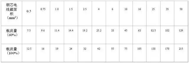
Select the wire cross-sectional area based on the load current of the electrical device. The general principle is:
For electrical devices that work for long periods, use wires with an actual current capacity of 60%; for electrical devices that work for short periods, use wires with an actual current capacity between 60% and 100%. Additionally, consider voltage drop and wire heating in the circuit to avoid affecting the electrical performance of the device and exceeding the allowable temperature of the wire. To ensure a certain mechanical strength, the cross-sectional area of low-voltage wires should generally not be less than 0.5 mm².
The following table shows the allowable current capacity of various copper core wires based on their nominal cross-sectional area.
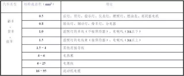
The following table shows the recommended values for selecting the cross-sectional area of wires in major circuits of automotive 12V electrical systems.
2. Wire Colors
To facilitate installation and maintenance, automotive wiring uses two-color wires, with the main color as the base color and the auxiliary color as the color band or spiral color band on the wire. When marking, the main color is listed first, followed by the auxiliary color. When selecting two-color wires, the power lines for each electrical system are single-color, while the rest are two-color, with the main colors of the two-color wires shown in the following table.
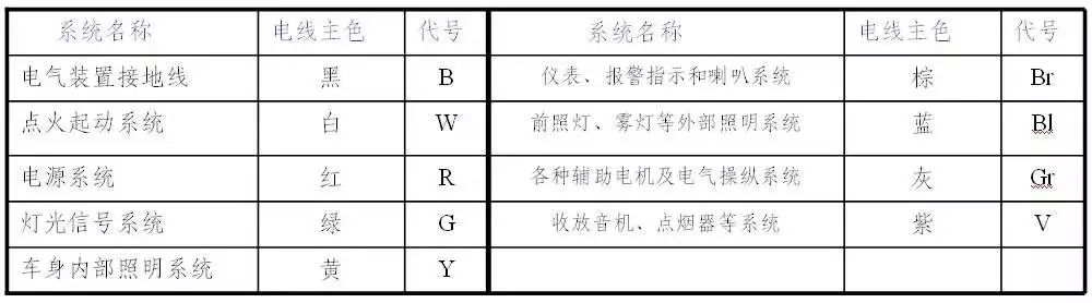
For two-color wires with a nominal cross-sectional area greater than 1.5 mm², the pairing of main and auxiliary colors is shown in the following table.
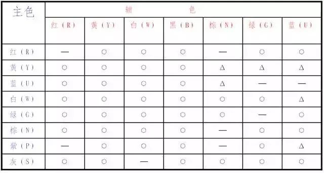
Note: ○ – Allowed color pairings; Δ – Not recommended color pairings.
Automotive Wiring Harness
To keep all vehicle wiring neat, facilitate installation, and protect the insulation of wires, the wiring in vehicles, except for high-voltage wires, battery cables, and starter cables, is generally bundled together using cotton yarn or thin PVC tape, called a wiring harness.
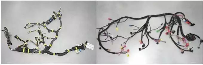
1. Bundling of Wiring Harnesses
1. Cable half-overlapping bundling method, applying insulating paint and drying it to increase the strength and insulation performance of the cable.
2. New type of wiring harness, partially plastic-wrapped and placed in a plastic corrugated pipe with side cutouts for higher strength, better protection, and easier troubleshooting.
2. Installation of Wiring Harnesses The wiring harnesses for the same model of vehicle are designed and manufactured in the factory, fixed at predetermined positions in the vehicle using clips or pins, with the taps located near the connection points of each electrical device. When installing, connect them to their corresponding terminals according to the wire numbers. The wiring harnesses for different models vary, and for the same model, they are divided into several harnesses based on the engine, chassis, and body.
Common Faults in Automotive Electrical Equipment Wiring
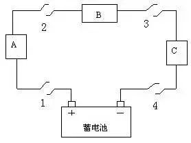
Open Circuit (Disconnection) Fault
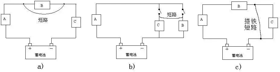
Short Circuit (Short Connection) Fault
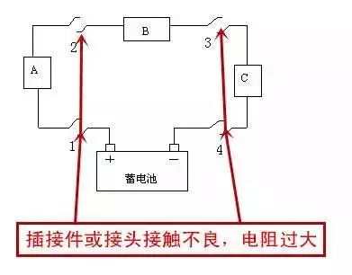
Poor Contact (Excessive Contact Resistance) Fault
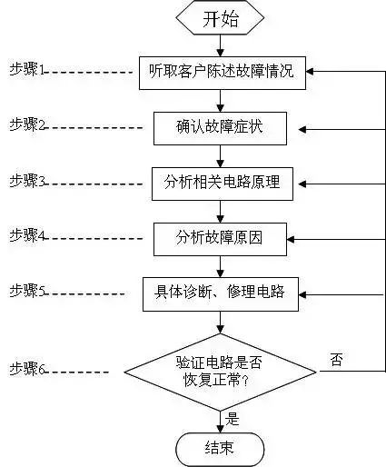
General Process for Diagnosing and Repairing Automotive Circuit Faults
A structured process is beneficial for beginners to develop good fault diagnosis and repair thinking. For maintenance personnel with considerable theoretical knowledge and work experience, it is not necessary to stick rigidly to the process steps in practical work; they can skip some steps based on actual situations or experience, going directly to the fault point for repair, effectively improving work efficiency.
Additionally, modern vehicles increasingly utilize microcomputer control systems, making it very quick to read fault codes and data streams using diagnostic tools for fault diagnosis, effectively narrowing down the fault range and even directly locating the fault. Therefore, for faults related to microcomputer control systems, it is advisable to prioritize using diagnostic tools.
Common Methods for Diagnosing and Repairing Automotive Circuit Faults
Visual Inspection Method
When a certain part of the automotive electrical system malfunctions, abnormal phenomena such as smoke, sparks, strange noises, burning smells, and high temperatures may occur. By using the human sensory organs (hearing, touch, smell, sight) to conduct a visual inspection of automotive electrical devices, it is possible to determine the fault location, greatly enhancing repair speed.
Fuse Inspection Method
When a fault occurs in the automotive electrical system, the first step is to check whether the fuses are intact. For example, if an electrical device suddenly stops working while driving and the fuse in that branch blows, it indicates a grounding fault in that branch. If a fuse in a certain system repeatedly blows, it indicates that there is likely a grounding fault in that system, and simply replacing the fuse is not sufficient.
Scraping Method
The scraping method, also known as the fire test method, is usually used to determine whether there is an open circuit in the wiring harness or wires. By disconnecting one end of an electrical device and touching it to a metal part of the vehicle (grounding), sparks can be observed to determine whether there is an open circuit.
Note: The scraping method should not be used to check automotive electronic circuits to avoid damaging electronic components.
Test Light Method
Using an automotive bulb as a temporary test light, check whether the wiring harness is open or shorted, and whether there are faults in the electrical devices or circuits. This method is particularly suitable for checking electrical devices with electronic components that do not allow direct shorting. When using the temporary test light method, be careful that the power of the test light is not too high, especially when testing whether the control (output) terminals of electronic controllers have output and sufficient output to prevent overloading and damaging the controller.
Short Circuit Method
The short circuit method, also known as the short connection method, involves using a wire to short a segment of wire or an electrical device and observing the changes in the electrical device.
Replacement Method
The replacement method is often used when the cause of a fault is complex, allowing for the elimination of potential causes one by one. The specific approach is to use a known good component to replace the suspected faulty component, allowing for testing of the suspicion. If the fault disappears after replacement, the suspicion is confirmed; otherwise, the original component is reinstalled, and new replacements are tested until the true fault location is found.
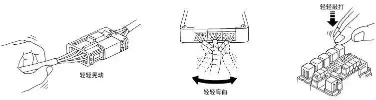
Simulation Method
1. Vehicle Vibration Simulation
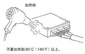
2. Thermal Sensitivity (Temperature) Simulation
Note: Do not heat electrical components above 60°C.
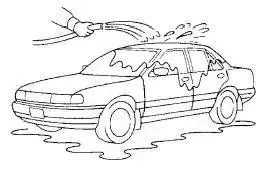
3. Water Immersion Simulation
Note: Do not spray water directly on electrical components.
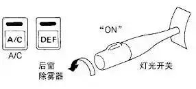
4. Electrical Load Simulation
5. Cold Start or Hot Start Simulation
In some cases, electrical faults may only occur during cold starts or after the vehicle has briefly shut down and then restarted.
Considerations for Diagnosing and Repairing Automotive Circuit Faults
The primary principle when repairing automotive electrical systems is not to randomly replace wires or electrical devices, as this could lead to short circuits or overloads, causing fires. Additionally, pay attention to the following:
1. When disconnecting the battery, always disconnect the negative (-) cable first; when connecting the battery, always connect the negative (-) cable last. Ensure that the ignition switch or other switches are turned off when disconnecting or connecting the battery cables to avoid damaging semiconductor components. Never reverse the polarity of the battery terminals.
2. It is permissible to use an ohmmeter and multimeter on the R×100 low-resistance ohm setting to test small power transistors to avoid current overload damaging them. When replacing transistors, connect the base first, and disconnect the base last. For metal-oxide semiconductor transistors (MOS), be cautious of electrostatic breakdown; when soldering, unplug the soldering iron from the power source.
3. Cut off the power supply when disassembling and installing components. Unless otherwise specified, the component leads should be at least 10mm away from the solder joints to avoid damaging the components, and it is advisable to use a temperature-controlled soldering iron or one with a power rating of less than 75W.
4. When replacing blown fuses, use fuses of the same specification. Using fuses with a higher specified capacity can lead to electrical damage or fire.
5. The wiring harness sections near vibrating components (such as the engine) should be secured with clips to tighten any loose sections, preventing the harness from touching other components due to vibration.
6. Do not handle electrical devices roughly or discard them carelessly. Whether the components are good or bad, they should be handled gently to avoid excessive shocks.
7. Wire sections that may rub against sharp edges should be wrapped with tape to prevent damage. When installing and securing components, ensure that the wiring harness is not pinched or damaged, and ensure that connectors are securely plugged in.
8. During maintenance, if temperatures exceed 80°C (such as during soldering), remove temperature-sensitive components (such as the ECU) first.
ENDEvaluation Center Free Application

👆Long press the image to scan and apply👆