1. Application Background and Measurement Objectives
In industrial manufacturing, cylindrical runout is a key indicator for assessing the machining accuracy of shaft-like parts (such as motor shafts, hydraulic cylinder piston rods, and precision bearing inner rings). It refers to the radial deviation of each point on the surface of a cylinder during rotation relative to the reference axis, mainly including:
- Round runout: The maximum radial deviation of all points on a single cross-section from the reference axis (reflecting the roundness and coaxiality errors of the cross-section);
- Total runout: The maximum radial deviation of all cross-sections along the entire length of the cylinder (comprehensively reflecting the errors of cylindricity, coaxiality, and straightness).
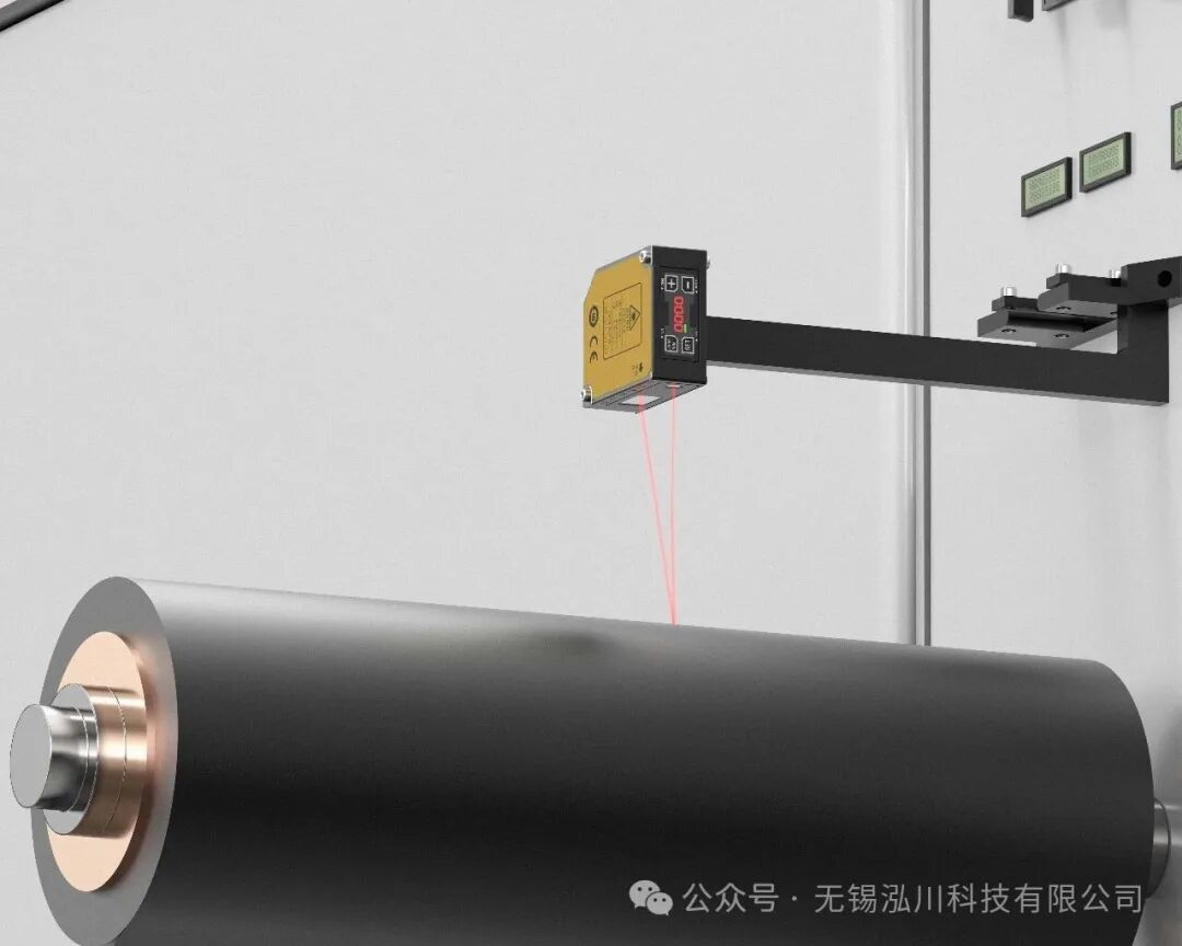
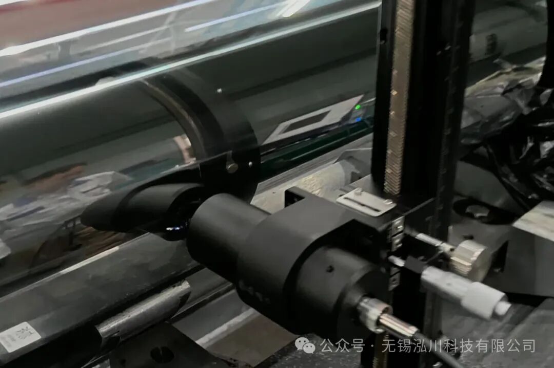
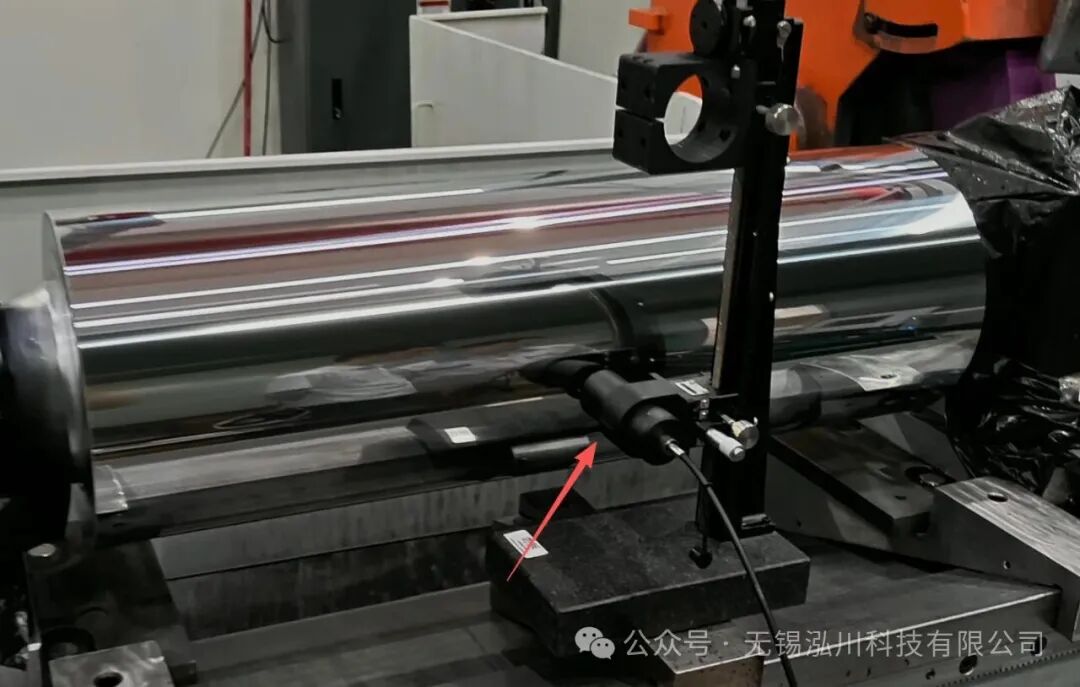
This case focuses on rotational cylinders with diameters ranging from 10 to 50 mm (such as automotive transmission input shafts), using both the Laser Displacement Sensor (LTP030 series) and the Spectral Confocal Sensor (LTC4000F series) to achieve runout measurement, comparing the adaptability and measurement effects of the two technologies.
2. Measurement System Composition
Based on the uploaded sensor parameters, two measurement systems were built, with the core hardware as follows:
| System Component | Laser Displacement Sensor System (LTP030 Series) | Spectral Confocal Sensor System (LTC4000F Series) |
|---|---|---|
| Core Sensor | LTP030U (Ultra-wide spot 35×1100μm, suitable for large diameter cylinders; IP67 protection) | LTC4000F (Focusing spot Φ16μm, high precision; requires controller) |
| Rotational Drive Device | Servo motor (speed 0-1000rpm, with encoder feedback for rotational angle) + centering fixture | Same as above, speed 0-500rpm (matching sensor sampling frequency) |
| Data Acquisition Module | Sensor with built-in RS485/TCP/IP interface (directly outputs distance data) | LT-CCH controller (up to 21KHz sampling rate, 16 channels available) |
| Tool Positioning | V-block + pin (ensures the reference axis of the cylinder coincides with the rotational axis) | Same as above, with an additional sensor fine-tuning bracket (suitable for 38mm measurement center distance) |
| Software and Computing Unit | Hongchuan supporting measurement and control software (including C# SDK) + industrial computer (i7 processor) | Same as above, with an additional spectral data filtering module |
3. Measurement Principles of the Two Sensors
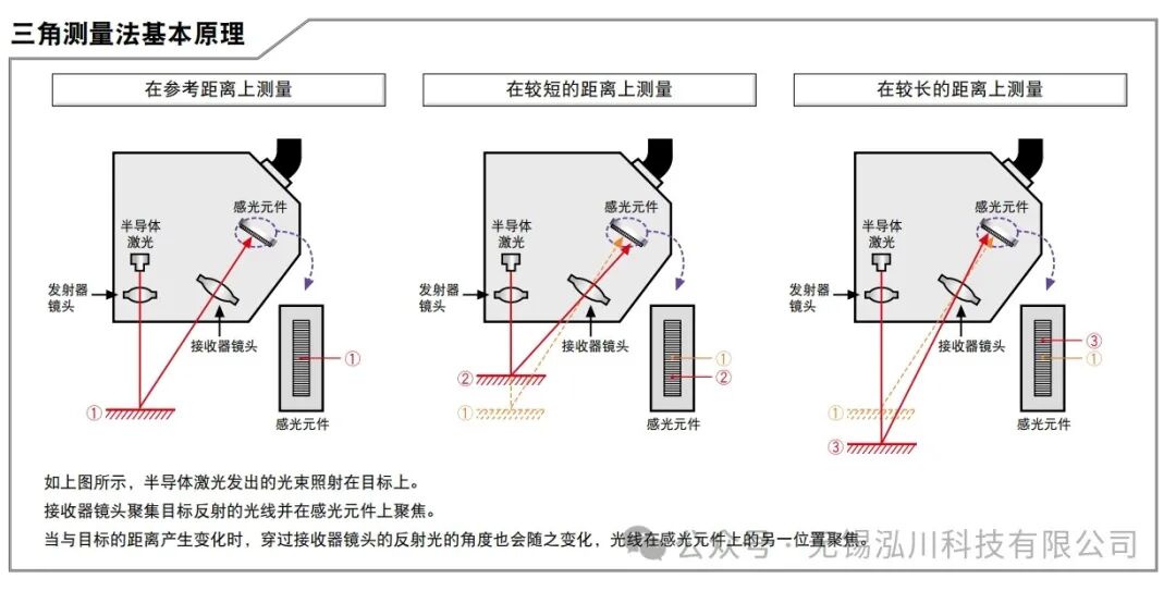
1. Laser Displacement Sensor (LTP030 Series: Laser Triangulation Method)
- Core Principle: Utilizes the triangular geometric relationship of “laser emission – surface reflection – receiver imaging” to calculate distance.
- The sensor emits a 655nm red semiconductor laser (Class 2 laser, 4.9mW), which is focused onto the surface of the cylinder through a lens (LTP030U spot size 35×1100μm, suitable for rough/large area surfaces);
- The laser beam reflected from the cylinder surface is imaged on a CMOS photosensitive array through a receiving lens, forming a light spot;
- As the cylinder rotates, the radial deviation of the surface causes the reflected light spot to shift position on the photosensitive array, and the real-time distance is calculated using the triangular formula (
<span>Distance ∝ Spot Shift / Trigonometric Function Value</span>).
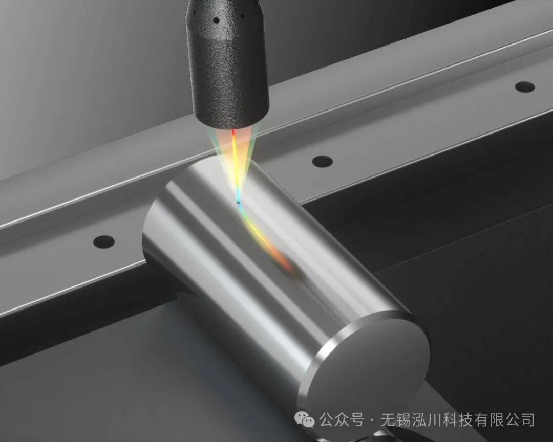
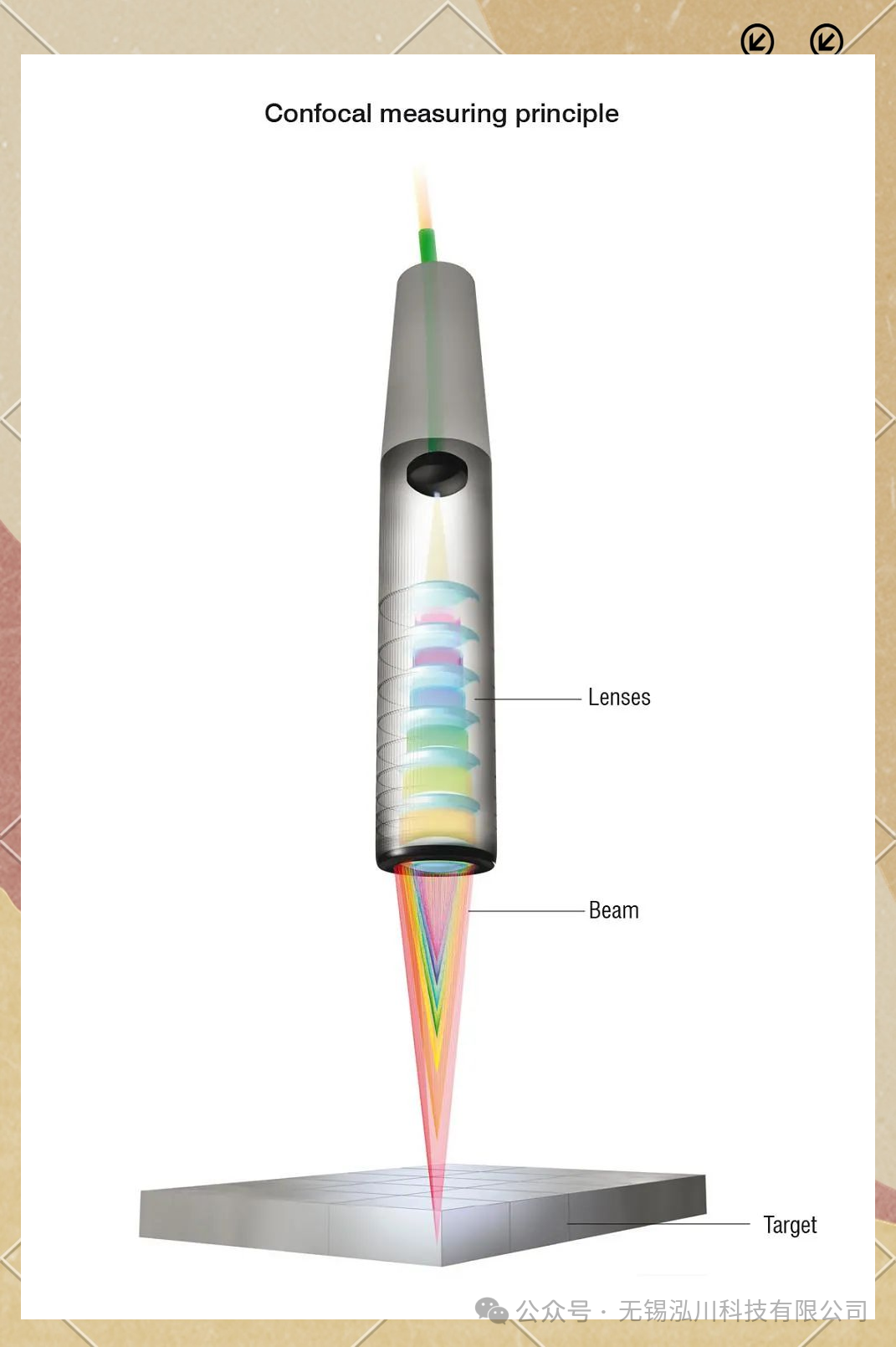
2. Spectral Confocal Sensor (LTC4000F Series: Spectral Confocal Method)
- Core Principle: Utilizes “multicolor light dispersion focusing + spectral analysis” to achieve distance measurement, independent of reflection angle.
- The sensor emits white light (containing monochromatic light of different wavelengths), which, after passing through a dispersive lens, focuses different wavelengths of light at different distances (wavelength corresponds to focusing distance);
- Among the reflected light from the cylinder surface, only the “monochromatic light focused on the surface” has the highest intensity, while other wavelengths have weaker intensity due to defocusing;
- The reflected light is analyzed by a spectrometer, extracting the intensity peak corresponding to the wavelength, and real-time distance is calculated using a preset “wavelength-distance” calibration curve (LTC4000F range 4000μm, ±2000μm detection range).
4. Detailed Measurement Steps
1. General Preparation Steps (Applicable to Both Systems)
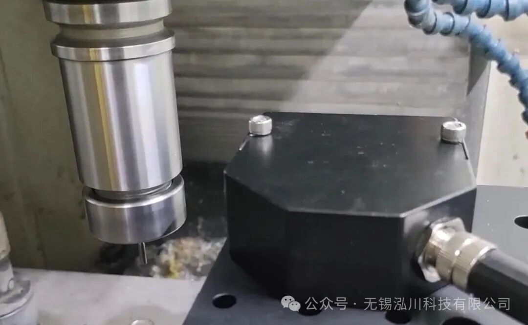
- Tool Installation: Fix the V-block and pin on the optical platform, adjust the pin spacing to ensure that the reference axis of the cylinder is coaxial with the rotational axis during rotation (coaxiality error < 0.001mm);
- Sensor Calibration:
- Laser Displacement Sensor (LTP030): Calibrate using a standard white ceramic sample (for repeatability testing), set the “0 point” (distance from sensor to sample = 30mm measurement center distance), and verify repeatability (within 0.15μm);
- Spectral Confocal Sensor (LTC4000F): Calibrate using a silver-coated mirror (for repeatability testing), set the “0 point” (distance from sensor to mirror = 38mm measurement center distance), and verify linear error using a laser interferometer ( < ±0.8μm);
2. Measurement Steps for Laser Displacement Sensor (LTP030U)
- Parameter Settings: Set the sampling frequency (50KHz, full range), response time (100μs), output mode (RS485 real-time output distance data) through the software, and enable the “laser off/sample hold” external input function (to prevent laser interference during non-measurement phases);
- Start Rotation: The servo motor drives the cylinder to rotate at a speed of 200rpm (each rotation time 0.3s, collecting 15000 points per rotation at 50KHz sampling rate, ensuring data density);
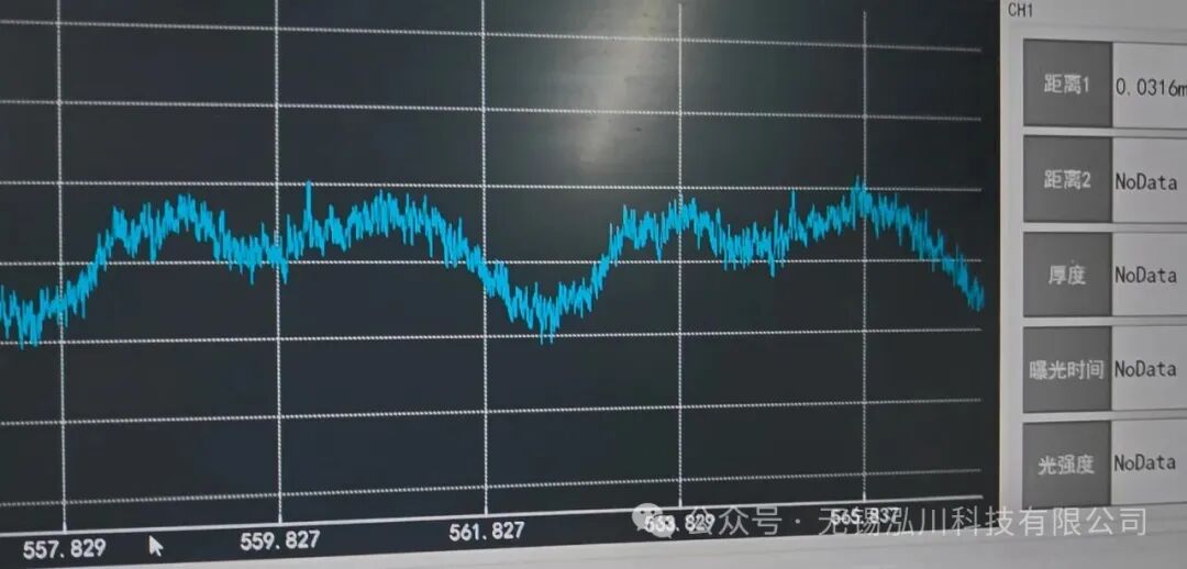
- Data Acquisition: The software synchronously collects “rotational angle (encoder feedback) – distance” data pairs, continuously collecting for 5 rotational cycles (to exclude random errors);
- Stop and Reset: After the motor stops, turn off the laser and save the data file (CSV format).
3. Measurement Steps for Spectral Confocal Sensor (LTC4000F)
- Controller Configuration: Set the sampling frequency (20KHz, matching motor speed), channel parameters (single-channel measurement, filter level 3) in the LT-CCH controller, and associate the sensor with the controller through the software (confirm FC/PC fiber connection is normal);
- Start Rotation: The servo motor drives the cylinder to rotate at a speed of 100rpm (each rotation time 0.6s, collecting 12000 points per rotation at 20KHz sampling rate, ensuring spectral data integrity);
- Data Acquisition: The controller receives spectral peak data in real-time, converts it to distance, and uploads it to the computer, continuously collecting for 8 rotational cycles (to compensate for minor fluctuations in spectral data);
- Stop and Calibration: After the motor stops, use a standard mirror to verify sensor accuracy again (deviation < 0.1μm) and save the data file.
5. Comparison of Advantages and Disadvantages of the Two Sensors
Based on measurement principles and actual application scenarios, combined with product parameters, the comparison of advantages and disadvantages is as follows:
| Comparison Dimension | Laser Displacement Sensor (LTP030 Series) | Spectral Confocal Sensor (LTC4000F Series) |
|---|---|---|
| Core Performance | – Speed: Up to 160KHz sampling rate (20% range reduction), 6.25μs response time – Precision: Repeatability of 0.15μm, linearity ±0.02% F.S. (10mm range) | – High precision: Repeatability of 0.1μm, linear error < ±0.8μm (4mm range) – Speed: Up to 21KHz sampling rate (dependent on controller) |
| Surface Adaptability | – Advantage: Suitable for diffuse reflective surfaces (such as cast iron, aluminum alloy shafts) – Disadvantage: Mirror/transparent surfaces may lose data due to reflection angle deviation (need to select wide spot model to mitigate) | – Advantage: No reflection angle limitation, can measure mirror surfaces (chrome, stainless steel), transparent materials (glass, acrylic) – Disadvantage: Sensitivity decreases for high light-absorbing surfaces (such as black plastic) |
| System Complexity and Cost | – Low complexity: Operates independently without a controller (IP67 protection, suitable for dusty environments) – Cost: Single sensor cost is about 1/3 of spectral confocal | – High complexity: Requires a controller (LT-CCH), fiber connection needs protection – Cost: High cost for single sensor + controller, suitable for high precision scenarios |
| Range and Installation | – Large range (10mm, ±5mm detection range), 30mm measurement center distance, high installation tolerance – Weight 287g, suitable for automation integration | – Small range (4mm, ±2000μm detection range), 38mm measurement center distance requires precise calibration – Weight 226g, requires additional support for fixing |
6. Data Acquisition and Runout Calculation Algorithm
1. Data Acquisition Methods (Differences Between the Two Systems)
| Sensor Type | Acquisition Interface | Data Format | Acquisition Frequency Matching Principle |
|---|---|---|---|
| Laser Displacement Sensor (LTP030U) | RS485/TCP/IP | Real-time distance value (mm, precision 0.1μm) | Sampling frequency ≥ rotational frequency × required points per rotation (e.g., 200rpm×1000 points/rotation = 3.3KHz, select 50KHz for redundancy) |
| Spectral Confocal Sensor (LTC4000F) | LT-CCH controller (Ethernet) | Wavelength + distance value (μm, precision 0.01μm) | Sampling frequency ≤ maximum frequency of controller (21KHz), and points per rotation ≥ 8000 (to ensure cross-section fitting accuracy) |
2. Runout Calculation Algorithm (General Steps)
Step 1: Data Preprocessing (Remove Anomalies and Denoise)
- Outlier Removal: Use the 3σ rule to calculate the mean μ and standard deviation σ of distance data within a single rotation cycle, removing data that exceeds
<span>[μ-3σ, μ+3σ]</span>(e.g., occasional reflective interference from the sensor); - Denoising Filtering: Laser displacement data uses “moving average filtering” (window size 5), spectral confocal data uses “Gaussian filtering” (σ=0.5) to reduce high-frequency vibration noise (e.g., slight motor jitter).
Step 2: Cross-Section Data Segmentation (This Step is Required for Total Runout Measurement)
- Take N measurement cross-sections along the axial direction of the cylinder (e.g., for a 100mm long cylinder, take 10 cross-sections with a spacing of 10mm), each cross-section corresponds to the preprocessed data of one rotation cycle (
<span>angle θi, distance di</span>, i=1~N).
Step 3: Fitting the Reference Circle Center (Least Squares Method)
- Convert the “angle – distance” data to Cartesian coordinates: Let the distance from the sensor to the reference axis be L (LTP030 takes 30mm, LTC4000F takes 38mm), then the Cartesian coordinates of a point on the cylinder surface are:
<span>xi = (L - di) × cosθi</span><span>yi = (L - di) × sinθi</span> - Fit the circle equation
<span>x² + y² + ax + by + c = 0</span>, solving for the circle center coordinates<span>(x0, y0) = (-a/2, -b/2)</span>and the fitted radius<span>R = √((a/2)²+(b/2)² - c)</span>.
Step 4: Runout Calculation
- Round Runout: The difference between the maximum radial deviation and the minimum radial deviation within a single cross-section:
<span>Round Runout = max(√(xi²+yi²) - R) - min(√(xi²+yi²) - R)</span>(Note:<span>√(xi²+yi²)</span>is the actual radius, and the deviation from the fitted radius R is the radial deviation) - Total Runout: The maximum value of round runout across all cross-sections, or the difference between the “maximum radial deviation” and “minimum radial deviation” across all cross-sections:
<span>Total Runout = max(max radial deviation of all cross-sections) - min(min radial deviation of all cross-sections)</span>
Example Calculation (Using LTP030U Measurement as an Example)
- Cylinder speed 200rpm, sampling frequency 50KHz, collecting 15000 points per rotation, θi=360°×(i-1)/15000 (i=1~15000);
- After preprocessing, the range of di is 29.995~30.005mm (L=30mm), converting to xi, yi gives a fitted circle center (0.0002, -0.0001) mm, R=0.005mm;
- The radial deviation range is -0.0003~0.0002mm, round runout = 0.0005mm (0.5μm);
- The maximum round runout of the 10 cross-sections is 0.6μm, thus total runout = 0.6μm.
7. Application Scenario Adaptation Suggestions
-
Preferred Scenarios for Laser Displacement Sensor (LTP030 Series):
- Mass production lines (e.g., motor shaft mass detection): require high-speed measurement (160KHz sampling rate), cost-sensitive, and the cylindrical surface is diffuse reflective (e.g., blackened shafts);
- Harsh environments (e.g., near machine tools, hydraulic workshops): IP67 protection can withstand dust/oil, and no controller reduces failure points.
Preferred Scenarios for Spectral Confocal Sensor (LTC4000F Series):
- Precision part inspection (e.g., aircraft engine shafts): runout requirement < 1μm, surface is mirror-like (chrome/polished);
- Measurement of transparent cylinders (e.g., medical catheters, glass light guide columns): laser triangulation method easily penetrates transparent materials, spectral confocal can accurately measure surface distance.
8. Conclusion
Both sensors have their advantages in measuring the runout of rotating cylindrical bodies: the laser displacement sensor adapts to mass production scenarios with “high speed, low cost, and high protection,” while the spectral confocal sensor adapts to precision/special material scenarios with “high precision and strong surface adaptability.” In practical applications, it is necessary to considerrunout precision requirements, cylindrical surface characteristics, and measurement speed needs when making a selection, and ensure the accuracy of runout calculations through “least squares fitting + multi-cycle data averaging” to ultimately meet quality control requirements in industrial manufacturing.
(Note: The sensor parameters in this case refer to the parameter tables of Hongchuan Technology’s LTP030 series and LTC4000F series, and specific applications need to adjust the sensor installation distance and sampling frequency based on actual cylinder dimensions.)