
1
Overview of Electric Vehicle Controllers
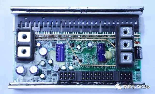
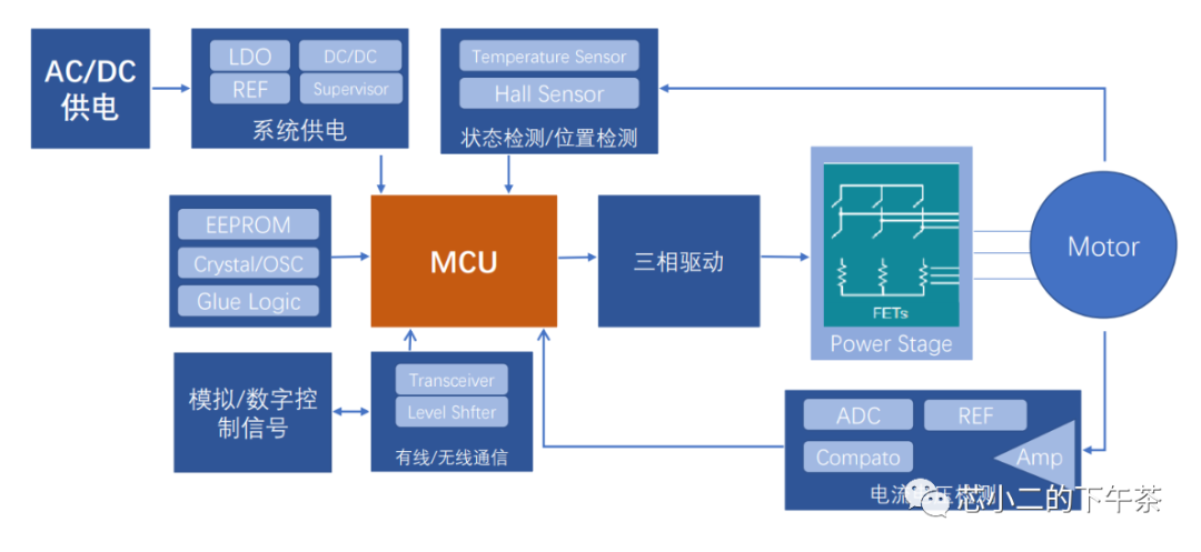
The two-wheeled vehicle controller, simply put, controls the motor, which mainly consists of two parts:
-
Hardware Core: AD sampling, CPU computation, PWM drive
-
Software Core: Motor control algorithms, such as square wave control and FOC control (dual-resistor FOC/single-resistor FOC)
2
MCU Rollout Method Used in Controllers
The first phase is still a cost competition for the MCUs themselves, improving the computational performance of the MCUs.Initially dominated by Renesas MCUs, the market later shifted to Taiwanese MCUs. With the advent of the ARM era, STM32 made a strong entry, with the STM32F103C6T6 capturing a significant market share.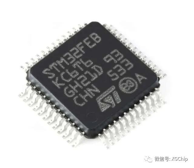 To compete on price, ST specifically rebranded to STM32FEBKC6T6 to target the electric vehicle market. With the launch of domestic XX32F103, the entire two-wheeled vehicle MCU market has roughly split into two branches:
- One branch continues to use the 8-bit microcontroller architecture, integrating some single-instruction hardware algorithm units on-chip, such as square root and single-instruction multiplication/division. This category is mainly dominated by companies like Zhongying and Fengzhan.
- The other branch consists of microcontrollers compatible with ST’s ARM core, primarily based on M3 and M4 cores, with many M0 cores emerging. They leverage ARM’s powerful internal resources for computational processing, directly competing with CBT6 in the market; with higher clock frequencies, larger memory, and 5V power supply, ST has been losing ground.
Currently, such MCUs can be priced under 2 RMB, with Yateli’s M4 core chips nearing that price, while those 8-bit microcontrollers are heading towards 1.5 RMB.The second phase involves integrating analog components and optimizing at the system level.As competition intensifies, domestic microcontroller design manufacturers have become more agile, adding operational amplifiers and comparators, significantly reducing overall costs for controllers. In addition to eliminating the need for external operational amplifiers and comparators, the layout of the entire controller has also become much simpler.
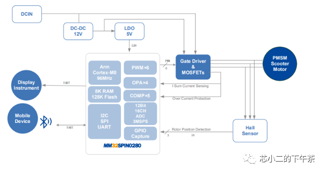 Source: Lingdong Micro
Note: In the image, current sampling eliminates resistors, relying directly on the internal resistance of the MOSFET; (currently, this approach is not mainstream, as the precision of built-in MOSFETs is not high).Similar companies like Lingou and Zhongwei have also launched high-integration chips with integrated operational amplifiers and comparators.Some manufacturers’ MCUs have even integrated MOS drivers, making the simplicity of having a microcontroller control six MOSFETs quite exciting.
3
How Sampling Circuits Evolve
Let’s look at how the peripheral sampling circuits evolve with the improvement of MCU clock frequency and algorithm optimization.
For current sensing, whether using power resistors + isolated operational amplifiers or Hall sensors, both are considered luxuries in the two-wheeled electric vehicle market, only used in some high-end scenarios.
Thus, technical optimization begins. We can choose to connect a sampling resistor between the lower MOSFET and the ground when the lower MOSFET is turned on, eliminating the need for an isolated operational amplifier and allowing normal low-voltage operational amplifiers to sample current, as shown in the figure below:
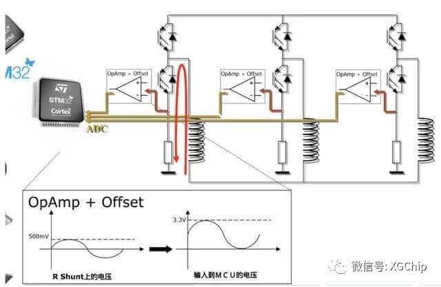
This design only requires controlling the ADC sampling moment when the lower MOSFET is turned on to obtain the line current; it complicates software but simplifies hardware by replacing three high-voltage isolated operational amplifiers with a regular 50-cent four-channel operational amplifier.
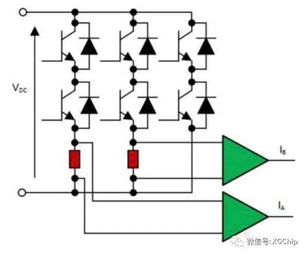
This is not the end; if we do not consider using full power, meaning there are no strict requirements for the modulation ratio of the bus voltage, we can reduce total power slightly, allowing us to sample complete current information with just two phase resistors + two operational amplifiers, thus saving an additional 30 cents.
Did you think this was the end?
A 3W surface-mounted power resistor costs about 0.25 RMB, and it generates heat; at higher power levels, multiple resistors need to be paralleled. Since MOSFETs have an internal resistance, can’t we just sample that instead?
Looking at the figure, I’ve removed the three power sampling resistors; we will directly calculate the current value using the internal resistance of the MOSFET when the lower MOSFET is turned on, and we can also perform some compensation using temperature detection when necessary.
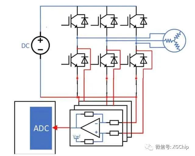
Look, isn’t this circuit board much simpler? Because it’s simpler, it’s cheaper.
However, this is still not enough savings, and the consistency of the MOS’s internal resistance varies with temperature, affecting current sampling precision.
To further optimize the software algorithm, we can use one sampling resistor to sample three-phase currents. This is the single-resistor sampling technology, as shown in the technical architecture below:
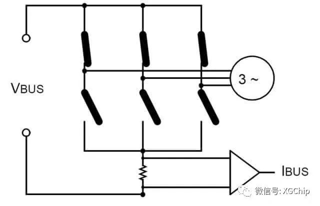
This single-resistor sampling reduces the cost of the entire sampling circuit to one power resistor + one regular operational amplifier, but it significantly increases the software requirements. We need to sample twice within a single FOC cycle waveform, which also puts demands on the ADC’s sampling speed.
As for how to determine the sampling moment and how to achieve waveform compensation, many proprietary technologies from chip manufacturers can be researched; I won’t elaborate on that here.
TI’s method also samples twice during the left half of the PWM cycle; when an unobservable zone occurs, if the current cycle is insufficient, it “advances” the value from the next cycle to compensate. There are many other methods; the goal of reducing costs and increasing efficiency has been achieved.
I believe every industry has its form of “involution”; as long as we achieve a tenfold improvement in cost or a tenfold enhancement in functionality, it is a great innovation.


 Click to read the original article and register for the event.