1. Design Concept:
Initially, power is supplied to the microcontroller via a manual key. The power indicator LED4 lights up, indicating that the microcontroller is running, and Relay 2 works to power the microcontroller. The working time of Relay 2 is set via a button, allowing the system to automatically cut off power. The working time of Relay 1 is set to achieve intermittent rotation of the fan, thereby saving energy.
1. Display Section: Through the button, the display switches between the fan rotation time, pause time, and the remaining time until the system shuts down. The digital display is two digits, showing minutes, while the remaining time until the system shuts down is shown in hours. The LEDs are red, yellow, and blue, corresponding to the states of fan rotation, pause, and remaining time until the system shuts down.
2. Button Section:
l K1 is the time adjustment shift key. When pressed, the digits flash, and the corresponding LED flashes. It switches between the fan rotation time, pause time, and the system.
l K2 is the increment and state switch display key. When K1 is pressed, it increments the time by 1. Otherwise, it switches the display between the fan rotation time, pause time, and the system.
l K3 is the decrement and standby key. When K1 is pressed, it increments the time by 1; otherwise, it is ineffective.
3. Relay Section:
l Relay 1 controls the power line of the fan, enabling rotation and pause.
l Relay 2 controls the power supply of the microcontroller system, allowing the system to shut down on a timer.
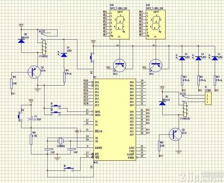
2. Schematic Diagram
3. Program Listing
/*********************************************
System Name: Simple Timer Controller for Fan
Creator: w418781840 Date: 2008.7.6
System Function:
**********************************************/
/*********************************************
Function Name: Declaration Area
Function Description:
**********************************************/
#include
#define uchar unsigned char
#define uint unsigned int
#define SEG P0 // Segment selection for digital tube.
#define DIG P2 // Position selection for digital tube
uchar dis[2]; // Digital drive group
uchar code TAB[]={ 0xC0,0xF9,0xA4,0xB0,0x99,//0-4 common anode.
0x92,0x82,0xF8,0x80,0x90,0xff};//5-9, off symbol
uchar start,stop,close,sum,time; // Basic variables
uchar fliflag,cflag,zflag,x,y;// Various flags
uint count_T0,count_T1,c_count; // Counting variables
sbit K1=P3^7; // Function shift key
sbit K2=P3^2; // Increment key and switch shift key.
sbit K3=P3^3; // Decrement.
sbit RLED=P2^2; // Red LED, indicates fan rotation status.
sbit YLED=P2^3; // Yellow LED, indicates fan pause status
sbit BLED=P2^4; // Blue LED, indicates system status
sbit CLED=P2^6; // Fan control bit
sbit ZLED=P2^7; // System work control bit
/*********************************************
Function Name: Delay 1MS Function
Function Description: Display call.
**********************************************/
void delay1ms(uchar x)
{
uchar i,j;
for(i=0;i for(j=0;j<120;j++);
}
/*********************************************
Function Name: Display Function
Function Description: Displays minutes, two digits.
**********************************************/
void display(void)
{
uchar i,scan=1;
for(i=0;i<2;i++)
{ SEG=0xff;
DIG=~scan;
SEG=TAB[dis[i]];
delay1ms(5);
scan<<=1;
}
}
/*********************************************
Function Name: Delay 5MS Function
Function Description: Key debounce call.
**********************************************/
void delay5ms(uchar x)
{
uchar j;
for(j=0;j display();
}
/*********************************************
Function Name: Initialization Function
Function Description: Initialize variables.
**********************************************/
void init()
{ fliflag=0;// Flashing flag.
cflag=1; // Fan state flag.
zflag=0; // Rotation flag.
x=30; // Temporary storage
y=10; // Temporary storage
CLED=1;// System working.
sum=0; // Shift
start=30; // Fan rotation time
stop=10; // Pause time.
close=5; // Remaining time until system shut down
count_T0=0; // T0, T1 related
count_T1=0;
c_count=0;
TMOD=0x11;
TH0=(65536-50000)/256;
TL0=(65536-50000)%256;
TH1=(65536-50000)/256;
TL1=(65536-50000)%256;
EA=1;
ET0=1;
ET1=1;
TR0=1;
}
/*********************************************
Function Name: Separation Function
Function Description: Separates tens and units for display
**********************************************/
void disnner(void)
{ if(cflag==1)//1
{ RLED=0;YLED=1;BLED=1;// Red LED flashes.
time=start; // Display rotation time.
}
if(cflag==2)
{ RLED=1;YLED=0;BLED=1;
time=stop;
}
if(cflag==3)
{ RLED=1;YLED=1;BLED=0;
time=close;
}
dis[0]=time/10;
dis[1]=time%10;
}
/*********************************************
Function Name: T0 Interrupt Function
Function Description: Generates 1 minute.
**********************************************/
void timer0(void)interrupt 1
{ TH0=(65536-50000)/256;
TL0=(65536-50000)%256;
if(++count_T0==1200)// One minute.
{ count_T0=0;
if(zflag==0) // If 0
{ ZLED=1; // Then rotate.
if(start!=99)// If rotation time is 99, display 99, do not switch flag. Rotate continuously.
{
start–; // If not, then countdown.
if(start==0)
{ zflag=1;// Countdown time reached. Switch flag.
cflag=2;
start=x;// Reassign value
}
}
}
else
{ ZLED=0; // Otherwise pause.
stop–; // Countdown counting.
if(stop==0)
{ cflag=1; // Time is up.
zflag=0;
stop=y;
}
}
if(close!=99)// If system time is 99, display 99, system keeps working..
{ if(++c_count==60) // Count 60 for one minute, that is, after one hour.
{ c_count=0;
close–; // Perform one hour countdown.
if(close==0) // Time is up, system cuts off power.
CLED=0; // Low level is effective.
}
}
}
disnner();// Separate. Send to display/
}
/*********************************************
Function Name: T1 Interrupt Service Function
Function Description: Used for adjusting time flashing.
**********************************************/
void timer1(void)interrupt 3
{
TH1=(65536-50000)/256;
TL1=(65536-50000)%256;
if(++count_T1==6)// Flashing period 30MS
{
count_T1=0;
fliflag=~fliflag; // Switch
if(fliflag==0) // Flag is effective.
{
if(sum==1)cflag=1;// Use state flashing.
if(sum==2)cflag=2;
if(sum==3)cflag=3;
disnner(); // For flashing.
dis[0]=10; // Show off symbol.
dis[1]=10;
}
else // Otherwise, normal display.
{
RLED=1;YLED=1;BLED=1;
dis[0]=time/10;
dis[1]=time%10;
}
}
}
/*********************************************
Function Name: Key Scanning Function
Function Description: Adjust time
**********************************************/
void scanner(void)
{ if(K1==0) // If 0, indicates a key is pressed.
{
delay5ms(100);// Delay 500MS.
if(K1==0) // Still pressed. Just released.
{
while(K1==0)display();// Wait for release.
delay5ms(2); // Debounce.
cflag=1; // Exit display state 1.
count_T0=0;
TR0=1; // Start T0
TR1=0; // Turn off flashing
sum=0; // Return to position.
x=start; // Temporary storage.
y=stop; // Temporary storage.
}
else
{ // Otherwise, a shift key is pressed.
TR0=0; // Stop time progression.
TR1=1; // Turn on flashing.
sum++; // Shift.
if(sum==4)
sum=1;
}
}
if(K2==0)
{
delay5ms(2);
if(K2==0)
{
while(K2==0)display();
delay5ms(2);
if(sum) // If there is a shift
{ if(sum==1)
{
start++;
if(start==61)
start=99;
if(start==100)
start=30;
}
if(sum==2)
{
stop++;
if(stop==61)
stop=5;
}
if(sum==3)
{
close++;
if(close==9)
close=99;
if(close==100)
close=1;
}
}
else // No shift.
{
cflag++; // Then perform display state shift.
if(cflag==4)
cflag=1;
}
}
}
if(K3==0)
{
delay5ms(2);
if(K3==0)
{
while(K3==0)display();
delay5ms(2);
if(sum==1)
{ start–;
if(start==29)
start=99;
if(start==98)
start=60;
}
if(sum==2)
{ stop–;
if(stop==4)
stop=60;
}
if(sum==3)
{ close–;
if(close==0)
close=99;
if(close==98)
close=8;
}
}
}
}
/*********************************************
Function Name: Main Function
Function Description:
**********************************************/
main()
{
init();
while(1)
{
display();// Display
scanner(); // Detect keys..
}
}