


Introduction to In-Vehicle Networks
As the complexity of electronic control systems increases, and the demand for communication capabilities among the electronic control units (ECUs) within vehicles grows, the use of point-to-point connections leads to an increase in wiring harnesses inside the vehicle. This creates significant challenges for reliability, safety, and quality in automotive design and manufacturing. Therefore, to reduce wiring and achieve data sharing and rapid exchange while improving product reliability, automotive electronic network systems based on rapidly developing computer networks, such as CAN, CAN-FD, and Ethernet, are implemented, referred to as in-vehicle networks.
1. CAN Controller Area Network
The CAN (Controller Area Network) bus was developed by Bosch in the early 1980s to solve data exchange issues between numerous control systems and testing instruments in modern vehicles. It is a multi-master bus, and the communication medium can be twisted pair, coaxial cable, or optical fiber. The maximum communication speed can reach 1 Mbps.
Characteristics of the CAN bus:
1) There is no master-slave distinction in data communication; any node can initiate data communication with any other (one or more) nodes, relying on the priority of the information from each node to determine the communication order, with higher priority nodes communicating in 134 ps.
2) When multiple nodes initiate communication simultaneously, lower priority nodes yield to higher priority ones, preventing congestion on the communication line.
3) The maximum communication distance can reach 10 km (at speeds below 5 kbps) and can reach 1 Mbps (when the communication distance is less than 40 m).
4) The transmission medium for the CAN bus can be twisted pair or coaxial cable. The CAN bus is suitable for high data volume short-distance communication or long-distance low data volume communication, requiring high real-time performance, used in multi-master, multi-slave, or equal node environments.
2. CAN-FD
CAN-FD (Flexible Data-rate) is an enhanced version of the CAN protocol, featuring higher data transfer rates and larger packet sizes.
Typically, the transmission rate of the CAN protocol is limited to 1 Mbps, with a packet size of 8 bytes. In contrast, the CAN-FD protocol supports higher transmission rates of up to 10 Mbps and larger packet sizes of up to 64 bytes.
Additionally, the CAN-FD protocol supports flexible rate adjustments, allowing dynamic switching between different data transmission rates to better meet the needs of various applications. However, the CAN-FD protocol requires higher hardware and software support compared to the CAN protocol, making it unsuitable for some application scenarios.
Characteristics of the CAN-FD bus:
1) It adopts the same event-triggered mode as CAN communication, making software development and porting easier.
2) The maximum data transmission rate can reach 5 Mbit/s, better meeting the requirements for high real-time and high data transmission rate applications.
3) Each frame message has a valid data field of 64 bytes, accounting for over 70% of the entire frame message information.
4) It is less expensive compared to emerging buses like Ethernet.
3. Ethernet In-Vehicle Ethernet
Traditional Ethernet protocols, which use carrier sense multiple access and collision detection technology, do not meet the real-time requirements of in-vehicle networks in terms of packet delay, ordering, and reliability. Therefore, the common in-vehicle local area networks are still based on CAN real-time field bus protocols. However, with the explosive development of automotive electronic technology and the increasing number of ECUs, multimedia signals are also incorporated into in-vehicle communication, making traditional in-vehicle buses with high real-time and low bandwidth increasingly unsuitable for the development trends of automotive electronics.
The Institute of Electrical and Electronics Engineers (IEEE) approved the first in-vehicle Ethernet standard, “100BASE-T1,” in 2016 after extensive research. It is based on Broadcom’s BroadR-Reach solution, using single-pair unshielded twisted pair cables at the physical layer and employing an optimized scrambling algorithm to reduce signal correlation and increase real-time performance, providing a high real-time bandwidth of 100 Mbps within the vehicle.
The communication quality of high-speed Ethernet in the automotive interference environment is also a crucial issue that needs to be examined. In the complex environment of vehicles, in-vehicle Ethernet must consider the impact of current surges and electromagnetic interference, which can lead to unstable network performance.

In-Vehicle Ethernet
The automotive industry is rapidly evolving, with new models featuring unparalleled innovative characteristics that require communication with vehicles, roadside infrastructure, the internet, and advanced in-vehicle infotainment systems. Vehicles are also equipped with sensor-based safety systems that can eliminate collisions, significantly enhancing traffic safety.
Most new features and applications rely on expensive and complex wiring and electronic devices that require large bandwidth, while these complex electronic devices must complete a large amount of intricate instructions and data transmission among themselves.
To address this issue, new automotive in-vehicle Ethernet specifications and technical protocols have emerged. In-vehicle communication networks based on Ethernet standard protocols will significantly reduce the cost and weight of the required wiring.
1. Ethernet Network Wake-Up
Ethernet ECU communication wake-up must be achieved through CAN. All Ethernet ECUs must first wake up the corresponding CAN interface communication before starting Ethernet communication and meet specific communication conditions (e.g., diagnostic refresh conditions and FOTA conditions).
2. Ethernet Network Protocol Architecture
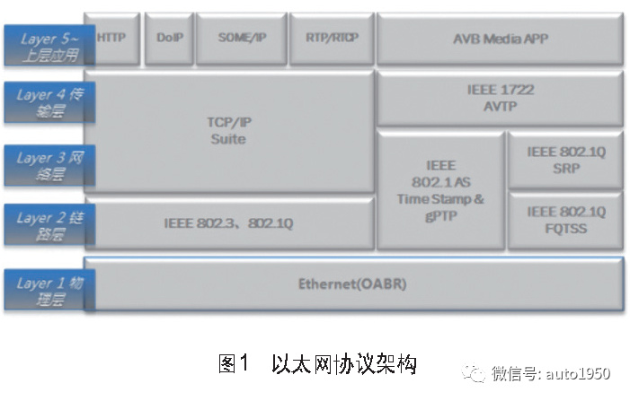
ECU Ethernet communication must support the network protocol architecture shown in Figure 1, where the transport layer and upper-layer application protocols can be selected according to actual functional requirements.
3. Standard Ethernet Interface Design
The circuit schematic must include the following components and their details: Ethernet transceiver, low-pass filter (optional), ESD, common mode choke, and common mode termination circuit (optional).
Relevant components in the above standard interface circuit must meet the OABR specification requirements.
4. Ethernet Transceiver
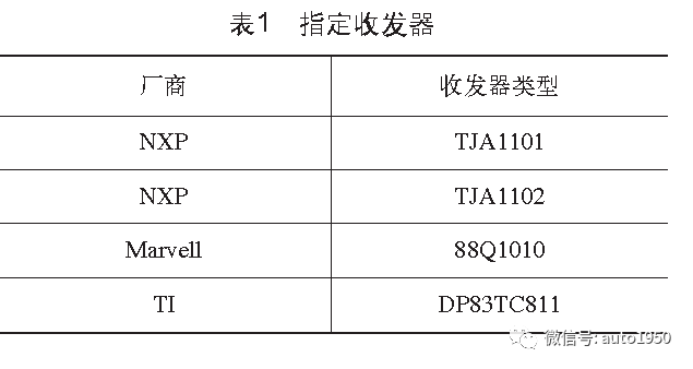
The transceiver and its dedicated integrated circuits must comply with IEEE802.3bw requirements, and only the transceivers specified in Table 1 may be used. Other models of transceivers must be confirmed with the host manufacturer before use.
5. Low-Pass Filtering
To suppress internal pulses, it is recommended to arrange a low-pass filter circuit at the output terminal of the transceiver. If this part of the circuit is already integrated within the transceiver, it does not need to be included in the interface circuit.
To ensure signal symmetry, all resistor components should have a tolerance of ±1%, and all capacitor components should have a tolerance of ±2%.
6. ESD
PCB design must consider ESD and over-voltage protection.
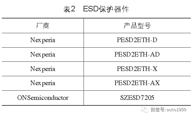
The ESD protection device models specified by the host manufacturer are detailed in Table 2, and other models of ESD protection devices must be approved by the host manufacturer before use. Note that both BR+ and BR- must be protected bidirectionally.
If some chip manufacturers have built-in ESD protection devices that meet the host manufacturer’s EMC-related testing requirements, no additional devices need to be added to the interface circuit, but ESD layout positions must be reserved.
7. Ethernet Common Mode Choke
To enhance EMC reliability and reduce noise radiation, a common mode choke (Ethernet choke) must be installed on the Ethernet twisted pair.
The Ethernet common mode choke must meet the OABR EMC Test Specification for Broad R-ReachTM Common Mode Chokes specification requirements.
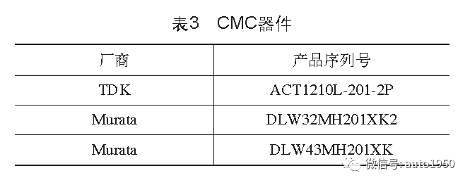
The list of Ethernet chokes specified by the host manufacturer is detailed in Table 3, and other models of Ethernet chokes must be approved by the host manufacturer before use.

Network Bus Load Calculation
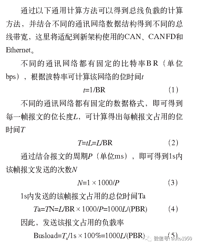
1. CAN Bus Load Calculation Method
Figure 2 shows the structure of a CAN frame. The CAN frame structure is divided into 8 fields: frame start, arbitration field, control field, data field, CRC field, ACK field, frame end, and ITM field.
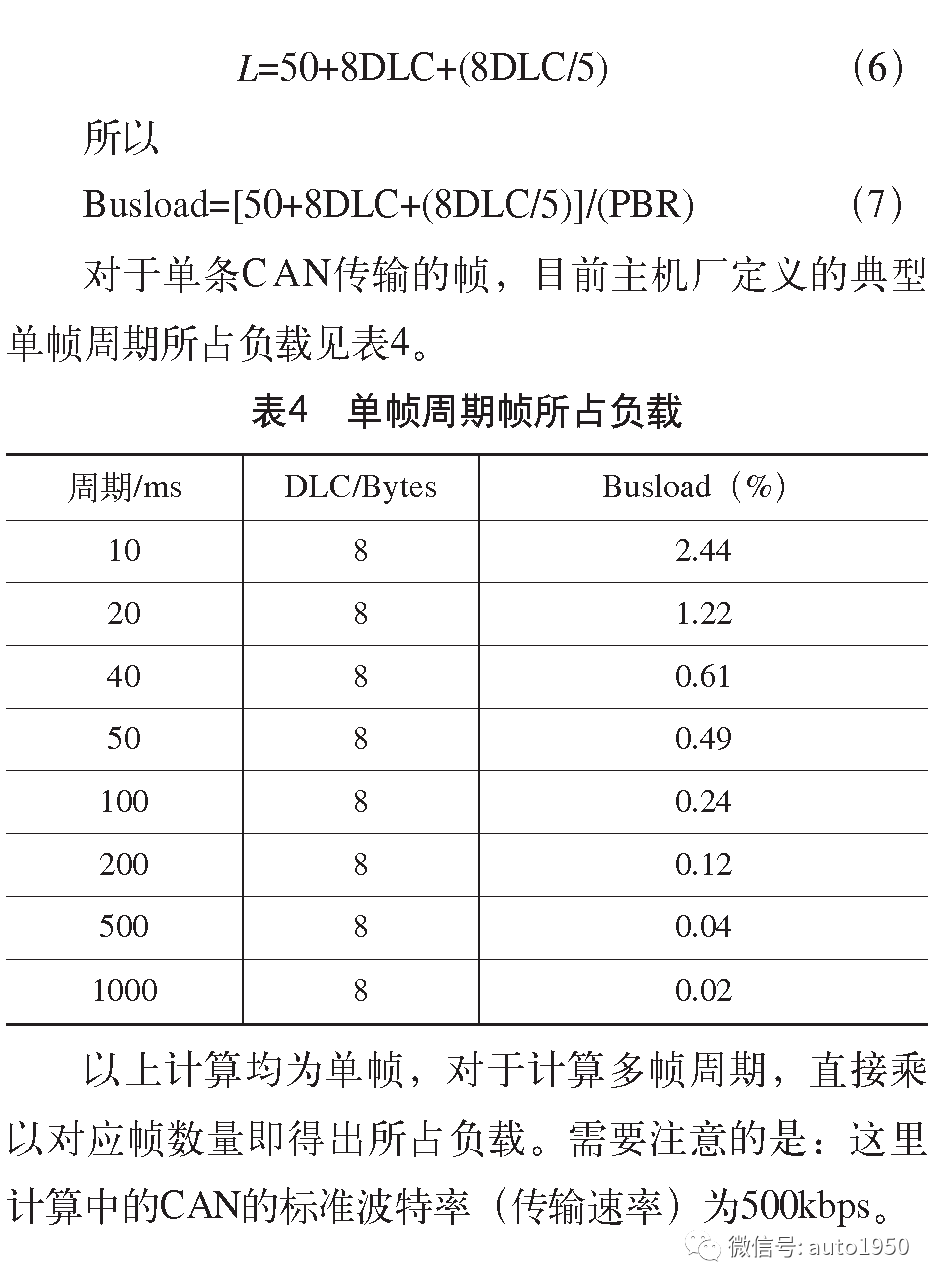
According to the CAN 2.0 specification established by Bosch, except for the frame end field and ITM field, the other parts of the CAN frame must comply with the bit filling rules. This rule states that if 5 consecutive dominant or recessive bits appear, a complementary bit must be filled. Among these, the total length of all fields except for the variable length data field that comply with the bit filling rule = 1 + 12 + 6 + 16 + 2 = 37 bits, and the maximum length of bit filling = 37/5 = 7 bits, so the maximum length of these fields can reach 37 + 7 = 44 bits. Adding the frame end and ITM fields, the maximum frame length is 44 + 7 + 3 = 54 bits. Here, the bit filling length is selected as the median value of 3, so the total length excluding the data field is 50 bits, making the total frame length…
2. CANFD Bus Load Calculation Method
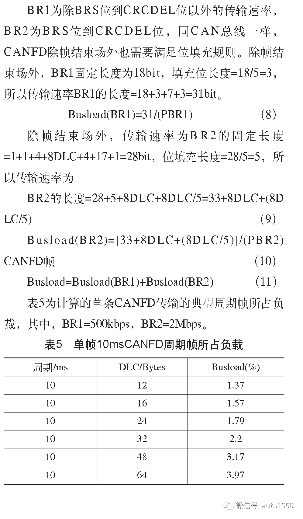
Figure 3 shows the CANFD frame structure, which is divided into arbitration field, control field, data field, CRC check field, ACK response field, and frame end field. One CANFD message can switch between two transmission rates, where the arbitration field and ACK field rate (BR1) are the same as traditional CAN, and the data field transmission rate (BR2) can reach up to 8 Mbps (generally 2M in the vehicle, 5 Mbps for OBD).

All calculations above are for a single frame; to calculate the load for multiple frame cycles, simply multiply by the corresponding frame count.
3. Ethernet Load Calculation Method
For the load calculation method of Ethernet, the new architecture will currently use service access-based transmission methods. Application functions such as FOTA/SOTA and diagnostics, similar to the periodic transmission methods of CAN/CANFD, cannot yet be determined whether they will be used. Here, the Ethernet frame load calculation methods for these two transmission methods are provided.
(1) Service Access-Based Transmission Method: This method is characterized by on-demand transmission, and the bandwidth occupied by the maximum data transmission can be calculated. It requires the fastest data transmission interval P, maximum data transmission speed BR, and data length L, to obtain Busload=L×8/(PBR), where data length L=14+8+20+DLC+5=63+DLC, with DLC being the application layer protocol data length, which needs to be combined with different application layer protocols.
(2) Periodic Transmission Method: This calculation method is the same as CAN/CANFD, by calculating the total bandwidth of periodic frames. First, calculate the single frame Busload=L×8/(PBR), and then accumulate the frames to obtain the total load of the entire Ethernet.
4. Example of Network Bus Load Calculation in Passenger Car Projects
When calculating the total bus load of the entire PT-CAN in Table 6, it is necessary to analyze the project architecture diagram. Here, an example of a passenger car project architecture is used to calculate the frames sent by nodes on PT-CAN and use the above method to sum up to obtain the total load of PT-CAN.


Conclusion
References:
[1] Ma Jian, Zhang Bingli, Huang Zhenfeng, et al. Design of Special Vehicle Architecture Based on In-Vehicle Ethernet [J]. Automotive Practical Technology, 2023, 48(4): 60-64.
[2] Ji Chunfan, Liu Jiahong, Mi Bin. Application of In-Vehicle Ethernet Technology [C]// China Intelligent Transportation Association. Proceedings of the 17th China Intelligent Transportation Annual Conference. Beijing: Mechanical Industry Press, 2022.
[3] Xiao Biao. Design and Manufacture of In-Vehicle Ethernet Cables [J]. Wires and Cables, 2022(5): 1-6.
[4] Xiao Wenping, He Aodong. Development Opportunities of In-Vehicle Ethernet in the Wave of Intelligent Networking [J]. Shanghai Automotive, 2023(4): 1-3.
Author: Ni Bin
Editor ▎ Wang Yan
Advertising Cooperation ▎ (WeChat same number)18240442679 Mr. Fu
☞ Golden Powder’s Favorite Book Rankings
☞ Mechanical Book Rankings
☞ Production Management Rankings
☞ Design Software Rankings

-
How to Publish an Article in the “Automotive Engineer” Annual Journal in 2023 -
In July 2023, New Energy Vehicles and Automotive Exports Continue to Show Good Momentum -
Domestic Solid-State Battery and Process Patents -
Large Automotive Supply Chain Behind Many Domestic Car Manufacturers, Recommended for Collection! -
Discussion on the Application Technology of Automotive Parts Processing Tools -
BYD will Supply Batteries to Tesla, Eight Major Processes of Blade Battery Production are Not Simple! -
What is the “4680” and “All-Solid Ear” Battery? Currently, No Company Dares to Publicly Disclose This Technology! -
3D Printing Tools Assist in Efficient Processing of Motor Housings and Transmissions -
It is a “Smart Level” Process Tool that Ensures Automotive Quality and is Indispensable in Industrial Production -
Necessity and Goals of Digital Factory Construction for New Energy Batteries -
5G Empowerment Recommended by Ren Zhengfei Has Been Published! This PPT Lets You Know All the Content. -
Great Wall Xushui Intelligent Factory: 286 Robots Create Luxury and Safety for VV5s

To Submit, Please Click the Above Image