In the previous introduction, we discussed aerospace data bus technology and noted that FC bus technology is considered one of the main data buses for the future development of aviation buses due to its high-speed data transmission characteristics, high reliability, and strong scalability. Therefore, in the upcoming articles, we will provide detailed introductions on aspects such as Fiber Channel technology, FC-AE series standards, FC-AE-1553, and FC standard clusters. In this issue, we will introduce the relevant technologies of Fiber Channel, including layered structure, topological structure, port types, service types, and port units.
1. Introduction to Fiber Channel
The Fiber Channel Avionics Environment (FC-AE) is a set of protocols developed by the Fiber Channel standard development organization, specifically designed for dedicated systems that can be used in the Fiber Channel avionics environment (including military and commercial applications). This protocol organically integrates fast and reliable channel technology with flexible and scalable network technology. The FC protocol has evolved to support many upper-layer protocols and instruction sets, such as: MIL-STD-1553B, IP, ATM, as well as HIPPI, IPI, SCSI instruction sets, and supports various physical media such as fiber and copper cables. The FC protocol effectively implements full-duplex, half-duplex, and simplex communication modes.
The basic characteristics of Fiber Channel are as follows:
-
High bandwidth, multi-media, and long-distance transmission: The serial transmission rate has increased from the initial 1Gbps to 4Gbps, and is advancing towards higher speeds and greater data throughput, suitable for large-scale data exchanges (such as audio and video data streams) between different modules; using fiber, copper cables, or shielded twisted pairs as transmission media, the low-cost copper cable transmission distance is 25m, multi-mode fiber transmission distance is 0.5km, and single-mode fiber transmission distance is 10km;
-
Reliability and real-time performance: Various error handling strategies, 32-bit CRC checks, utilizing different priorities to adapt to different message requirements, and resolving conflicts during medium access control, with a transmission error rate of less than 10-12, and end-to-end transmission delay of less than 10us, supporting non-acknowledged mode and sensor data transmission;
-
Uniformity and scalability: Nodes can be easily added or removed to meet different application needs, with a flexible topological structure that supports multi-level system interconnection, and enhanced compatibility and adaptability through high-level protocol mapping. Protocols such as SCSI, IP, ATM can be mapped to Fiber Channel to effectively reduce the variety of physical devices and additional equipment and lower economic costs;
-
Open interconnection, adhering to unified international standards.
Fiber Channel (FC) is a high-throughput, low-latency, packet-switched, and connection-oriented network technology. The entire standard series is continuously evolving, with the protocol specifications for the aviation field – Fiber Channel Avionics Environment (FC-AE) having customized 5 types, namely: Anonymous Message Transfer without Signature (FC-AE-ASM), MIL-STD-1553 High-Level Protocol (FC-AE-1553), Virtual Interface (FC-AE-VI), FC Lightweight Protocol (FC-AE-FCLP), and Remote Direct Memory Access Protocol (FC-AE-RDMA).
2. Fiber Channel Layered Structure
Fiber Channel is primarily divided into 5 layers (FC-0 to FC-4), similar to the seven-layer model structure of OSI and the four-layer model structure of TCP/IP, with the FC protocol having a five-layer model structure. The FC-0 interface and media layer define the physical link and characteristics; the FC-1 transport protocol layer defines the encoding/decoding scheme, byte synchronization, and ordered sets; the FC-2 link control layer defines the rules and mechanisms for transmitting block data; the FC-3 provides general services; and the FC-4 protocol mapping layer defines the method of mapping high-level protocols to low-level protocols. The protocol layering is shown in Figure 1:
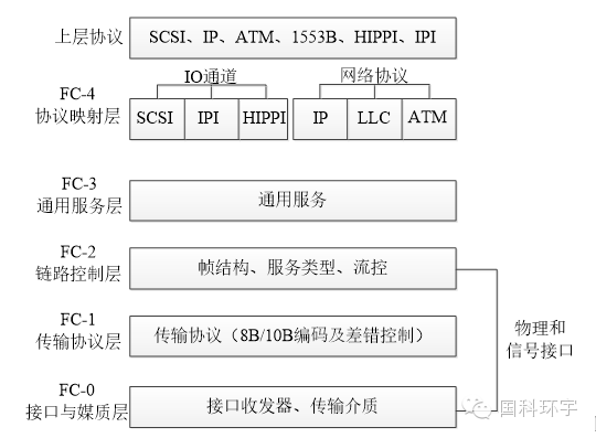 Figure 1 Fiber Channel Layered Structure Diagram
-
The FC-0 layer describes the physical interface, including transmission media, transmitters, and receivers and their interfaces. The FC-0 layer specifies various media and related devices that can operate at various rates;
-
The FC-1 layer describes the 8B/10B encoding, which separates control bytes from data bytes and simplifies bit, byte, and byte synchronization;
-
The FC-2 layer is the signaling protocol layer, which specifies the rules and mechanisms for transmitting block data. Within the protocol, the FC-2 layer is the most complex, providing different types of services, packetization, ordering, error checking, and reassembly of transmitted data;
-
The FC-3 layer provides a set of services shared by multiple N ports of Fiber Channel nodes;
-
FC-4 layer provides mapping of Fiber Channel capacity to existing upper-layer protocols.
3. Fiber Channel Topological Structure
Fiber Channel defines 3 types of topological structures: Point-to-Point, Arbitrated Loop, and Fabric topologies, as shown in Figure 2.

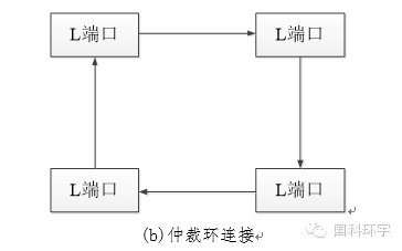
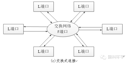
Figure 2 Fiber Channel Topological Structure Diagram
Point-to-point connection is the simplest of the three structures, as shown in Figure 2 (a), directly connecting the ports of two devices via optical cables, providing maximum bandwidth and enabling full-duplex connections, suitable for connecting nodes with high continuous data transmission requirements.
The arbitrated loop can connect up to 126 devices at high speed, with data transmitted in one direction around the loop. At any given time, only one pair of ports communicates in the arbitrated loop, and devices in the loop can only obtain the right to use the arbitrated loop when it is idle. A mesh structure of one or more arbitrated loops can form a hybrid structure. The arbitrated loop can serve as a connection between external storage devices in airborne systems or between display arrays. A hub-style ring mode can be used to improve the reliability of the ring connection, and if port bypass functionality is added, it can bypass faulty nodes, further enhancing the reliability of the entire ring.
The fabric network is the most powerful, reliable, and high-performance topology among the three, capable of connecting up to 16 million devices and allowing multiple devices to communicate at high speed simultaneously, although it is more expensive. In a single connection channel, the switch can simultaneously establish shared connection links and multiple direct connection channels, allowing for both packet switching and circuit switching. Each terminal’s port is interconnected with the switch port via point-to-point bidirectional connections, and each port can connect to the switch’s port at maximum speed.
Fiber Channel can be configured into a hybrid network of the above three types as needed, providing maximum flexibility.
4. Fiber Channel Port Types
In the Fiber Channel protocol, a port is the basic unit of communication. A port is a hardware entity within a node that communicates data with adjacent ports through the Fiber Channel link. Depending on the port’s position and topological structure, the Fiber Channel protocol defines the following types of ports:
-
N Port: The N port is the starting point and entry for the entire network, the simplest port in the Fiber Channel protocol, whose correct functionality directly determines whether the network operates normally;
-
F Port: Implemented in Fiber Channel switches, providing management and connection services between N ports, acting as a data relay in the Fiber Channel network;
-
L Port: The L port exists in the Fiber Channel ring network, where nodes in the ring share a common connected Fiber Channel ring network, aimed at reducing the bandwidth costs of the fiber network;
NL Port and FL Port: The FL port is implemented on switches, joining the Fiber Ring network as a special node, while the NL port is located within the ring structure, possessing dual capabilities of both N port and L port.
5. Fiber Channel Service Types
Fiber Channel defines 6 categories of services, largely depending on the type of data being transmitted. The main distinction between service categories is the use of different flow control types. If communication occurs between two N-Ports or if an N-Port registers to a switched network, at least one class of common service support is required, as sequencing and switching require class 1 service, and information is exchanged during the registration process of the switched network and N-Port.
-
Class 1 Service: Dedicated connection. The dedicated connection established by Class 1 service must be maintained and guaranteed by the switch, which will send frames to the destination N port in the order of the source N port’s transmission sequence.
-
Class 2 Service: Multiplexed connection. Class 2 service is a connectionless service that requires sending link control frames for acknowledgment after receiving data frames. Within a given sequence, the transmitter sends Class 2 data frames in continuous order, but the switch may not guarantee ordered delivery.
-
Class 3 Service: Datagram. Class 3 service is a connectionless service that only supports unacknowledged transmission, without sending any link control frames for acknowledgment after receiving valid data frames. Within a given sequence, the transmitter sends Class 3 data frames in continuous order, but the switch may not guarantee ordered delivery.
-
Class 4 Service: Partial bandwidth. By utilizing switch-managed partial bandwidth allocation protocols, Class 4 service uses virtual circuits established between the switch and two communicating N ports to send frames to each other. Within a given sequence, the transmitter sends Class 4 data frames in continuous order, and the switch sends frames to the destination N port in the same order as the source N port’s transmission sequence.
-
Class 5 Service: Class 5 service is used for synchronous, real-time services. However, it has not been fully defined yet and may be deprecated.
-
Class 6 Service: Multicast connection. Class 6 service allows one N port to establish simultaneous dedicated connections with multiple N ports. Once the dedicated connection is established, it must be maintained and guaranteed by the switch. The data flow of Class 6 can only go from the source N port to the destination N port. All destination N ports will send appropriate link response frames to a multicast server, which will collect these link response frames and return a single link response frame to the source N port.
6. Fiber Channel Data Units
Fiber Channel frames and signaling protocols define 3 types of protocol data units: Frame, Sequence, and Exchange, with their hierarchical relationships illustrated in the diagram.
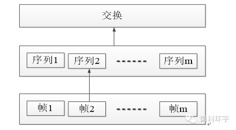
Figure 3 Hierarchical Relationship Diagram between Fiber Channel Frames and Signaling Protocols
Each frame follows a general frame format, as shown in the diagram.
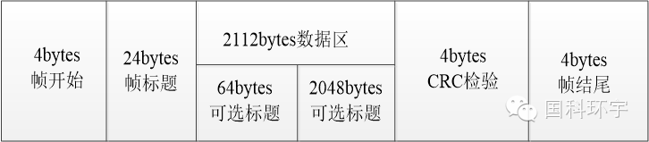 Figure 4 Frame Format Illustration
Each frame includes a start delimiter, a fixed frame header of 24 bytes, multiple operational service headers, a flexible payload length ranging from 0 to 2112 bytes, a frame standard cyclic redundancy check, and an end delimiter. A sequence is one or more related frames transmitted unidirectionally from one N port to another, and it is transmitted unidirectionally. An exchange consists of one or more non-concurrent sequences, which can be either unidirectional or bidirectional.
7. Conclusion
This issue provided a detailed introduction to Fiber Channel technology in response to the needs for the future development of aerospace data buses. In the next issue of “FC Bus Technology Introduction (Part 2)”, we will sort and introduce the FC-AE series standards, and provide detailed introductions and analyses of FC-AE-ASM, FC-AE-RDMA, FC-AE-VI, and FC-AE-1553 technologies.
Source: Guoke Huanyu