Skip to content
Click the above↑ “Lao Wang Talks to You AboutElectrical” FollowMe
1. System Selection and Architecture
Depending on the scale and layout of the venue, consider adopting a bus-based, distributed, or a combination of bus-based and distributed emergency broadcasting system architecture to fully leverage the advantages of both, meet the broadcasting needs of different areas, and ensure the system’s reliability and scalability.
(1) Bus-Based Broadcasting Subsystem
For areas that are relatively concentrated, well-defined, and have a relatively uniform distribution of broadcasting points, a bus-based broadcasting system is adopted.
1. Equipment Configuration
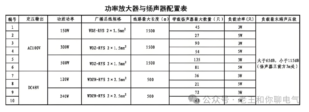
The bus-based emergency broadcasting controller serves as the core control unit of this subsystem, responsible for managing and coordinating the operation of the entire subsystem. Configure the number of broadcasting controllers reasonably according to the coverage area and the load capacity of the power amplifiers. Each broadcasting controller can connect to a maximum of 15 power amplifiers, which include constant voltage output AC100V and constant voltage output DC48V types, selected according to actual needs.
Power amplifiers are selected based on the power requirements of the broadcasting area. The constant voltage output AC100V power amplifier is suitable for general broadcasting scenarios, while the constant voltage output DC48V power amplifier should be prioritized in areas with high safety requirements, such as densely populated and frequently active places.
The broadcasting controller and the power amplifier are connected via a broadcasting bus using flame-retardant or fire-resistant cables to ensure the safety of the wiring in emergencies such as fires.
When the broadcasting bus uses the constant voltage AC100V scheme, it can connect one output, which can be branched. However, it should be noted that the total length of the line from the last speaker on the broadcasting bus to the power amplifier that outputs the bus should not exceed 1500m, and the wire diameter specification should be 1.5mm² or above to ensure audio signal transmission quality and power loss within a reasonable range.
(2) Distributed Broadcasting Subsystem
For areas with more dispersed building layouts, complex zoning, or extremely high reliability requirements for the broadcasting system, a distributed broadcasting system is adopted.
1. Equipment Configuration
The distributed emergency broadcasting controller serves as the core of the distributed subsystem, possessing stronger network communication capabilities and distributed management functions. Each broadcasting controller can carry a maximum of 30 power amplifiers and also supports both constant voltage output AC100V and constant voltage output DC48V power amplifiers.
The configuration principle for power amplifiers is similar to that of the bus-based subsystem, selected and distributed according to the actual situation of different areas to ensure that each area can obtain sufficient audio power support.
The wiring of the distributed broadcasting system mainly includes network wiring and audio line wiring. The network wiring uses standard Category 5 or 6 unshielded twisted pair cables to construct a stable Ethernet communication network, connecting broadcasting controllers and various distributed broadcasting nodes (including power amplifiers) to ensure the rapid and accurate transmission of broadcasting instructions.
When the broadcasting bus uses the constant voltage DC48V scheme, it can connect three outputs, but the three broadcasting buses cannot be branched. The length of a single broadcasting bus should not exceed 500m, and the wire diameter specification should be 2.5mm² or above. The total load of the three output buses should not exceed the design limit to ensure stable transmission of audio signals and power matching under safe voltage.
2. System Capacity and Redundancy Design
At the beginning of system design, fully consider the changes in on-site power load and future expansion needs, reserving 20% power redundancy. By reasonably selecting power amplifiers and accurately calculating the power requirements of the broadcasting area, ensure that the system can operate stably under various conditions, avoiding issues such as insufficient broadcasting volume or equipment damage due to insufficient power.
2. Broadcasting Controller Expansion
Whether it is a bus-based or distributed broadcasting subsystem, when the broadcasting controller carries more than the maximum allowable number of power amplifiers, timely increase the corresponding broadcasting controller to ensure the normal operation of the system and the reliability of broadcasting functions. For example, when the bus-based broadcasting controller carries more than 15 power amplifiers, it is advisable to add another bus-based broadcasting controller; when the distributed broadcasting controller carries more than 30 power amplifiers, it is advisable to add another distributed broadcasting controller.
3. Speaker Layout and Selection
According to the functional zoning, personnel distribution, and architectural characteristics of the venue, reasonably layout speakers. In densely populated areas, such as lobbies, corridors, and conference rooms, appropriately increase the density of speakers to ensure that the broadcast sound can be clearly and evenly covered to every corner. At the same time, consider the installation height and angle of the speakers to avoid sound obstruction and reflection, improving sound propagation effectiveness.
Select speakers that match the output voltage and power of the power amplifier to ensure the speakers can operate normally and meet the expected sound pressure level requirements. For different environments and venues, choose speakers with corresponding protection levels, clear sound quality, and high reliability, such as indoor ceiling speakers, wall-mounted speakers, and outdoor waterproof speakers, to meet the broadcasting needs of different areas.
4. System Interaction and Control
1. Interaction with Fire Alarm System
The emergency broadcasting system should closely interact with the automatic fire alarm system. When the fire alarm controller receives a fire alarm signal, it immediately sends a linkage instruction to the emergency broadcasting system. The emergency broadcasting system automatically starts the broadcasting controllers and power amplifiers in the corresponding area according to the pre-set linkage logic, playing emergency broadcasting information such as fire alarm sounds and evacuation instructions to guide personnel for safe evacuation.
2. Manual Control Function
In addition to the automatic linkage function, the emergency broadcasting system should also be equipped with manual control devices. For example, setting up a broadcasting control console in the fire control center allows operators to manually select broadcasting areas, playback content, and control volume, enabling flexible responses to various emergencies to ensure effective use of the broadcasting system.