 PLC Programming Thinking for Experts
 How to Design Modular Upper Computers?
 Why is there such a big difference in the situation of engineers in China and abroad?
 Learn TIA Portal SCL Programming Easily: Structured Variables
 Understand S7-1500 PLC Reading and Writing SQL Microsoft Database in Seconds
CAN (Controller Area Network) is a serial communication network that enables distributed real-time control.
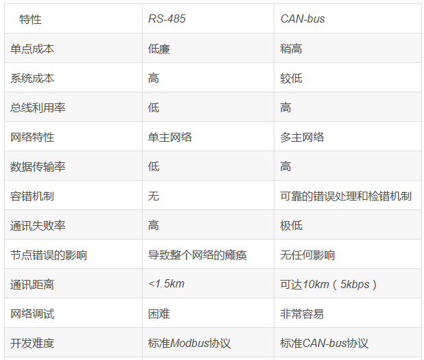
Comparison of CAN Bus and RS485 Bus
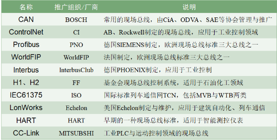
The popular buses currently are as follows:
Characteristics of CAN Bus:
1. An internationally standardized industrial field bus, reliable transmission, and high real-time performance; 2. Long transmission distance (up to 10Km) and fast transmission rate (up to 1MHz bps); 3. A single bus can connect up to 110 nodes, and it is easy to expand the number of nodes; 4. Multi-master structure, with equal status for all nodes, facilitating regional networking and high bus utilization; 5. High real-time performance, non-destructive bus arbitration technology, and no delay for high-priority nodes; 6. Faulty CAN nodes will automatically shut down and disconnect from the bus, without affecting bus communication; 7. Messages are short frame structures with hardware CRC checks, low probability of interference, and extremely low data error rates; 8. Automatic detection of message transmission success or failure, with hardware automatic retransmission, ensuring high transmission reliability; 9. Hardware message filtering function, only receiving necessary information, reducing CPU load, and simplifying software programming; 10. Communication media can use ordinary twisted pairs, coaxial cables, or optical fibers; 11. The CAN bus system structure is simple and has a very high cost-performance ratio.
Characteristics of RS485 Bus:
1. The electrical characteristics of RS-485: Logic “1” is represented by a voltage difference of + (2-6)V between the two wires; Logic “0” is represented by a voltage difference of – (2-6)V. The interface signal level is lower than RS-232-C, making it less likely to damage the interface circuit chips, and this level is compatible with TTL level, facilitating connection with TTL circuits; 2. The maximum data transmission rate of RS-485 is 10Mbps; 3. The RS-485 interface uses a combination of balanced drivers and differential receivers, enhancing common-mode rejection and noise immunity; 4. The maximum transmission distance of RS-485 is 4000 feet, practically reaching 3000 meters. Additionally, RS-232-C only allows one transceiver on the bus at a time, i.e., single-station capability. In contrast, RS-485 supports up to 128 transceivers on the bus, allowing users to easily establish a device network using a single RS-485 interface. However, only one transmitter can send at any time; 5. Due to the good noise immunity, long transmission distance, and multi-station capabilities, RS-485 is the preferred serial interface; 6. As the RS485 interface forms a half-duplex network, it generally requires only two wires, so RS485 interfaces use shielded twisted pairs for transmission.
Comparison of CAN Bus and RS485:
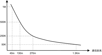
1. Speed and Distance: Both CAN and RS485 can transmit at a high rate of 1Mbit/S for distances not exceeding 100M. However, at low speeds, CAN can reach 10KM at 5Kbit/S, whereas RS485 can only reach approximately 1219 meters even at the lowest rates (without repeaters). Thus, CAN has a significant advantage in long-distance transmission.
2. Bus Utilization: RS485 is a single master-slave structure, meaning only one master can exist on the bus, initiating all communications. It does not issue commands, and subordinate nodes cannot send data until they receive a response from the master. This is to prevent multiple nodes from sending data simultaneously, causing data confusion. In contrast, CAN bus is a multi-master structure, with each node having a CAN controller. When multiple nodes send data, they automatically arbitrate based on the sent ID number, ensuring that bus data does not get mixed up. Moreover, once a node finishes sending, it can detect that the bus is idle and send immediately, eliminating the need for the master to inquire, thereby improving bus utilization and speed. Therefore, systems with high reliability requirements, such as automotive systems, predominantly use CAN bus or similar buses.
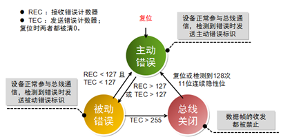
3. Error Detection Mechanism: RS485 only specifies the physical layer, lacking a data link layer, making it unable to recognize errors except for physical errors like shorts. This can lead to a situation where a faulty node continuously sends data, causing the entire bus to become paralyzed. Thus, if one node fails, the entire RS485 network goes down. On the other hand, CAN bus has a CAN controller that can detect any errors on the bus. If it detects more than 128 errors, it will automatically lock itself to protect the bus. If it detects errors from other nodes or itself, it will send an error frame to inform other nodes that the data is erroneous, prompting caution. Therefore, in networks where safety is paramount, CAN is very robust.
4. The CAN bus connects to the physical bus via two outputs, CANH and CANL, from the CAN controller interface chip 82C250. The CANH end can only be in a high level or floating state, while the CANL end can only be in a low level or floating state. This ensures that issues like short circuits caused by multiple nodes sending data simultaneously on the RS-485 network do not occur, which could damage certain nodes. Additionally, in severe error situations, CAN nodes have an automatic shutdown output function to prevent operations of other nodes on the bus from being affected, thus avoiding a “deadlock” state in the network due to issues with individual nodes.
5. CAN has a comprehensive communication protocol that can be implemented through CAN controller chips and their interface chips, significantly reducing system development difficulty and shortening development cycles. This is something that RS-485, which only has electrical protocols, cannot compare to.
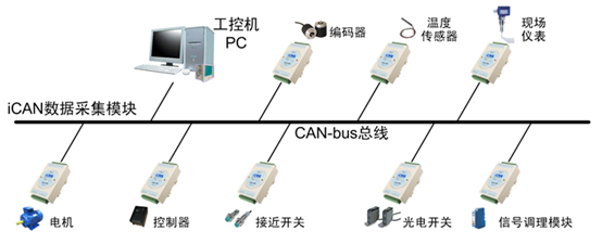
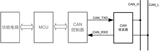
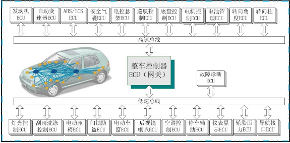
When thinking of CAN, one must think of Bosch, as CAN was developed by this company (along with Intel). CAN has many excellent characteristics, which allow it to be widely used. For instance: transmission speeds up to 1Mbps, communication distances up to 10km, lossless arbitration mechanisms, and multi-master structures. In recent years, the prices of CAN controllers have dropped significantly, and many MCUs now integrate CAN controllers. Nowadays, every car is equipped with a CAN bus. Below is a typical application scenario for CAN:
CAN bus standards only specify the physical layer and data link layer, requiring users to define the application layer. Different CAN standards only differ in the physical layer.
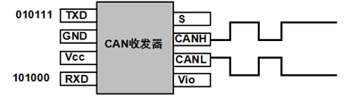
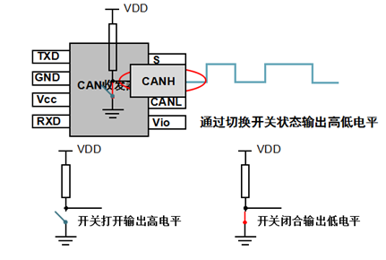
CAN transceivers are responsible for the conversion between logical levels and physical signals.
They convert logical signals into physical signals (differential levels) or vice versa.
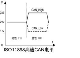
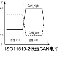
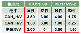
There are two CAN standards, namely IOS11898 and IOS11519, which differ in their differential voltage characteristics.
Low high and low level amplitudes correspond to faster transmission speeds;
*Twisted pair common-mode interference is mitigated because the levels change simultaneously, keeping the voltage difference unchanged.
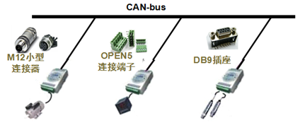
CAN has three types of interface devices
Multiple nodes are connected, and as long as one is low level, the bus is at low level. Only when all nodes output high level is the bus at high level. This is known as “wired AND”.
After 5 consecutive identical bits on the CAN bus, an opposite bit is inserted to create a transition edge for synchronization, eliminating cumulative errors.
Like 485 and 232, the transmission speed of CAN is inversely proportional to the distance.
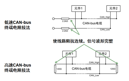
CAN bus, terminal resistance connection:
Why 120Ω? Because the characteristic impedance of the cable is 120Ω, simulating an infinitely long transmission line.
CAN bus transmits CAN frames, which are divided into five types: data frames, remote frames, error frames, overload frames, and frame intervals.
Data frames are used for sending and receiving data between nodes and are the most commonly used frame type; remote frames are used for receiving nodes to request data from sending nodes; error frames are used to notify other nodes of frame errors; overload frames are used by receiving nodes to inform sending nodes of their own receiving capabilities; and frame intervals are used to isolate data frames and remote frames from preceding frames.
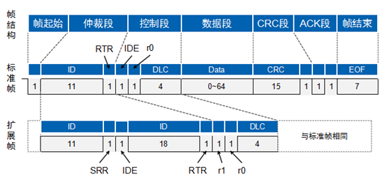
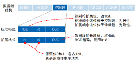
Data frames are divided into standard frames (2.0A) and extended frames (2.0B) based on arbitration segment length.
Frame start consists of one dominant bit (low level), sent by the transmitting node, with other nodes synchronizing to the frame start;
The frame end consists of seven recessive bits (high level).
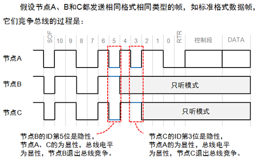
How does CAN bus solve the problem of multi-point contention?
The answer is given by the arbitration segment.
The CAN bus controller monitors the bus level while sending data. If the level differs, it stops sending and performs other processing. If this bit is in the arbitration segment, it exits the bus contention; if it is in another segment, it generates an error event.
The smaller the frame ID, the higher the priority. Since the RTR bit of the data frame is dominant, while that of the remote frame is recessive, in the case of the same frame format and ID, data frames take precedence over remote frames. Additionally, the IDE bit of the standard frame is dominant, while that of the extended frame is recessive, meaning that for standard and extended frames with the same first 11 bits of ID, the standard frame has a higher priority than the extended frame.
Consisting of 6 bits, the control segment of the standard frame includes the extended frame flag IDE, reserved bit r0, and data length code DLC; the control segment of the extended frame includes IDE, r1, r0, and DLC.
0-8 bytes, short frame structure, good real-time performance, suitable for automotive and industrial control fields;
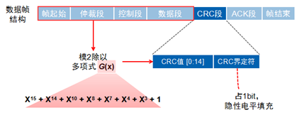
The CRC check segment consists of a 15-bit CRC value and a CRC delimiter.
When the receiving node receives the frame start to the CRC segment without error, it will send a dominant level in the ACK segment, while the sending node sends a recessive level, resulting in a dominant level on the line.
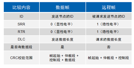
Remote frames consist of 6 segments and can be standard or extended frames, with the RTR bit set to 1 (recessive level).
CAN is a highly reliable bus, but it also has five types of errors.
CRC Error: Occurs when the transmitted and received CRC values differ;
Format Error: Occurs when the frame format is invalid;
Acknowledgment Error: Occurs when the sending node does not receive acknowledgment during the ACK phase;
Bit Sending Error: Occurs when the sending node detects that the bus level does not match the sending level during transmission;
Bit Filling Error: Occurs when communication rules are violated on the communication cable.
When any of these five errors occur, the sending or receiving node will send an error frame.
To prevent certain nodes from continuously sending error frames and interfering with other nodes’ communications, the CAN protocol specifies three states and behaviors for nodes.
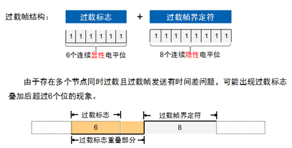
When a node is not ready to receive, it will send an overload frame to notify the sending node.
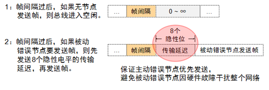
Used to isolate data frames and remote frames from preceding frames; error frames and overload frames do not have frame intervals preceding them.
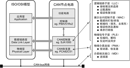
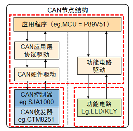
Building nodes to implement corresponding controls can be divided into four parts from bottom to top: CAN node circuit, CAN controller driver, CAN application layer protocol, and CAN node application program.
Although different nodes perform different functions, they all share the same hardware and software structure.
CAN transceivers and controllers correspond to the physical layer and data link layer of CAN, completing the sending and receiving of CAN messages; functional circuits complete specific functions, such as signal acquisition or controlling peripherals; the main controller and application software parse messages according to the CAN message format to complete corresponding controls.
CAN hardware drivers run on the main controller (e.g., P89V51) and mainly perform the following tasks: register-based operations, initializing the CAN controller, sending CAN messages, and receiving CAN messages;
If the CAN hardware driver is used directly, when the controller is replaced, the upper application program needs to be modified, leading to poor portability. By adding a virtual driver layer between the application layer and hardware driver layer, differences between different CAN controllers can be masked.
A CAN node not only performs communication functions but also includes some specific hardware functional circuits. The functional circuit drives the functional circuit directly downward while providing control function circuit function interfaces upward for the application layer. Specific functions include signal acquisition and human-machine display, etc.
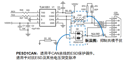
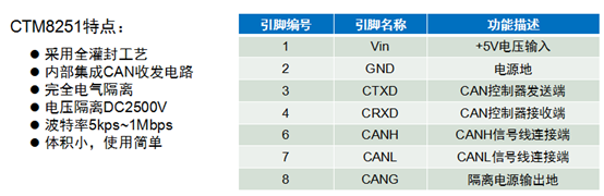
CAN transceivers implement the interchange between the logical levels of the CAN controller and the differential levels on the CAN bus. There are two solutions for implementing CAN transceivers: one is to use CAN transceiver ICs (requiring power isolation and electrical isolation), and the other is to use CAN isolation transceiver modules. The latter is recommended.
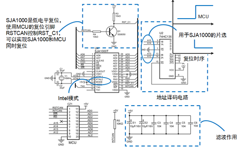
CAN controllers are the core components of CAN, implementing all functions of the data link layer of the CAN protocol and automatically completing the parsing of the CAN protocol. There are generally two types of CAN controllers: controller ICs (SJA1000) and MCUs with integrated CAN controllers (LPC11C00).
MCUs are responsible for controlling the functional circuits and CAN controllers: initializing CAN controller parameters upon node startup; reading and sending CAN frames through the CAN controller; handling CAN controller interrupt exceptions when they occur; outputting control signals based on received data;
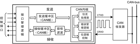
Interface management logic: interprets MCU instructions, addresses the register units of various functional modules in the CAN controller, and provides interrupt and status information to the main controller.
The transmission and reception buffers can store complete information on the CAN bus network.
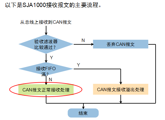
Acceptance filtering compares the stored verification code with the CAN message identifier, allowing only CAN frames that match the verification code to be stored in the reception buffer.
The CAN kernel implements all protocols of the data link.
Overview of CAN Protocol Application Layer
CAN bus only provides reliable transmission services, so when nodes receive messages, they must use application layer protocols to determine who sent the data and what the data represents. Common CAN application layer protocols include: CANOpen, DeviceNet, J1939, iCAN, etc.
CAN application layer protocol drivers run on the main controller (e.g., P89V51) and define the CAN messages according to the application layer protocol, completing the parsing and assembly of the CAN messages. For example, we use the frame ID to represent the node address; when the received frame ID does not match its own node ID, it is discarded; otherwise, it is passed to the upper layer for processing; when sending, the frame ID is set to the address of the receiving node.
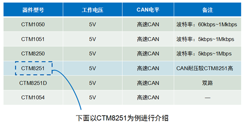
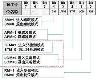
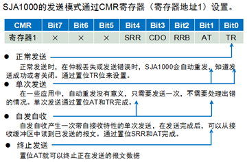
The output mode of SJA1000 has many options, with the most commonly used being the normal output mode. The input mode usually does not select the comparator mode, which can increase communication distance and reduce current in sleep mode.
Transceivers are divided into high-speed CAN transceivers and fault-tolerant CAN transceivers based on communication speed.
All CAN transceivers used in the same network must be the same.
CAN connection lines will have many interference signals, requiring hardware filters and anti-interference circuits to be added.
It is also possible to use CAN isolation transceivers (integrating filters and anti-interference circuits).
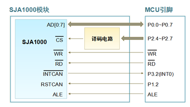
Connection Method of CAN Controller and MCU
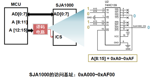
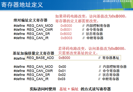
SJA1000 can be regarded as external RAM with an address width of 8 bits, supporting up to 256 registers.
#define REG_BASE_ADDR 0xA000 // Register base address
unsigned char *SJA_CS_Point = (unsigned char *) REG_BASE_ADDR ;
// Write to SJA1000 register
void WriteSJAReg(unsigned char RegAddr, unsigned char Value) {
*(SJA_CS_Point + RegAddr) = Value;
return;
}
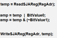
// Read from SJA1000 register
unsigned char ReadSJAReg(unsigned char RegAddr) {
return (*(SJA_CS_Point + RegAddr));
}
Continuously write data from the buffer to registers
…… for (i=0;i<len;i++) { WriteSJAReg(RegAdr+i,ValueBuf[i]); }……
Continuously read multiple registers into the buffer
……for (i=0;i<len;i++) { ReadSJAReg(RegAdr+i,ValueBuf[i]); }……
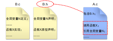
Header file inclusion scheme:
-
Each program includes the header files it uses
-
Each program includes a common header file, which contains all other header files
#ifndef __CONFIG_H__ // Prevent header file from being included multiple times
#define __CONFIG_H__
#include <8051.h>         // Include 80C51 register definition header file
#include "SJA1000REG.h"         // Include SJA1000 register definition header file

// Define byte operations
#define LOW_BYTE(x)  (unsigned char)(x)
#define HIGH_BYTE(x)  (unsigned char)((unsigned int)(x) >> 8)

// Define oscillator clock and processor clock frequency (users can adjust based on actual conditions)
#define OSCCLK 11059200UL
// Macro definition for MCU clock frequency
#define CPUCLK (OSCCLK / 12)
#endif // __CONFIG_H__
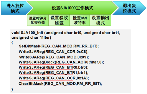
SJA1000 is in reset state after power-on and must be initialized before it can function.
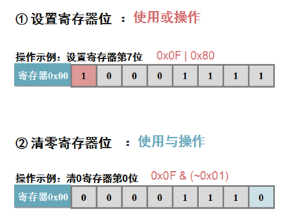
(1) Set the mode register Bit0 to enter reset mode;
(2) Set the clock division register to select clock frequency and CAN mode;
(3) Set acceptance filtering, defining the verification code and mask code;
(4) Set the bus timer registers 0 and 1 to define the CAN baud rate;
(6) Clear the mode register Bit0 to exit reset mode;
Listen-only mode: SJA1000 does not check the acknowledgment bit when sending CAN frames;
Listen mode: In this mode, SJA1000 will not send error frames, used for automatic baud rate detection; SJA1000 receives CAN frames at different baud rates. When a CAN frame is received, it indicates that the current baud rate matches the bus baud rate.
CAN bus has no clock and uses asynchronous serial transmission; baud rate refers to the number of data bits sent per second;
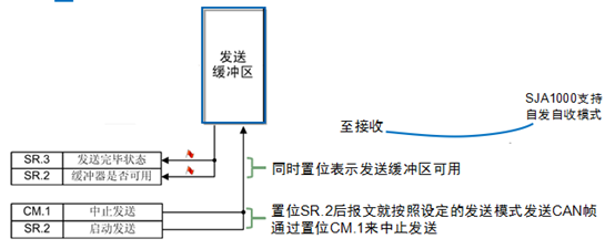
Sending CAN Frames:
Steps to send a CAN frame: 1. Check the status register and wait for the sending buffer to be available;
2. Fill the message into the sending buffer;
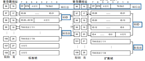
SJA1000 has a 12-byte buffer, and messages to be sent can be written through registers 16-28, or read from or written to registers 96-108.
char SetSJASendCmd(unsigned char cmd) {
unsigned char ret;
switch (cmd) {
default:
case 0:
        ret = SetBitMask(REG_CAN_CMR, TR_BIT); // Normal sending
break;
case 1:
        ret = SetBitMask(REG_CAN_CMR, TR_BIT|AT_BIT); // Single send
break;
case 2:
        ret = SetBitMask(REG_CAN_CMR, TR_BIT|SRR_BIT);// Self-send
break;
case 0xff:
        ret = SetBitMask(REG_CAN_CMR, AT_BIT);// Stop sending
break;
    }
return ret;
}
unsigned char SJA_CAN_Filter[8] = { // Define acceptance filter parameters, receive all frames
0x00, 0x00, 0x00, 0x00,
// ACR0~ACR3
0xff, 0xff, 0xff, 0xff
// AMR0~AMR3
};
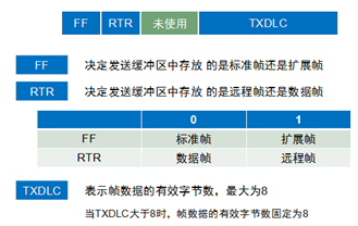
unsigned char STD_SEND_BUFFER[11] = { // CAN sending message buffer
0x08, // Frame information, standard data frame, data length = 8
0xEA, 0x60, // Frame ID = 0x753
0x55, 0x55, 0x55, 0x55, 0xaa, 0xaa, 0xaa, 0xaa // Frame data
};
void main(void) // Main function, program entry{
timerInit();// Initialization
D1 = 0;
SJA1000_RST = 1; // Hardware reset SJA1000
timerDelay(50); // Delay 500ms
SJA1000_RST = 0;
SJA1000_Init(0x00, 0x14, SJA_CAN_Filter); // Initialize SJA1000, set baud rate to 1Mbps
// Infinite loop, main() function cannot return
for(;;) {
SJASendData(STD_SEND_BUFFER, 0x0);
timerDelay(100); // Delay 1000ms
}
}
The reason the frame ID is 0x753 is related to how CAN frames are stored in the buffer.
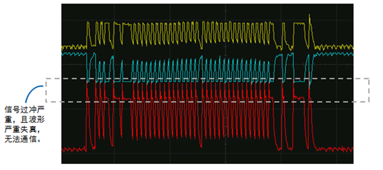
Terminal resistors are very important; when the baud rate is high and terminal resistors are not added, signal overshoot can be severe.