
1. Abstract
The drilling process is one of the most important components of the entire printed circuit board (PCB). Parameters such as hole position accuracy, hole diameter tolerance, and hole wall roughness directly affect the quality of the PCB and the reliability of product performance. Therefore, strict control of relevant quality items is required during the production process.This article mainly analyzes the causes of quality issues such as hole offset, breakout holes, short slot holes, skewed holes, and rough holes, and proposes improvement methods.2. PCBDrilling Quality Defects and Improvement Analysis1. Hole Offset1.1. Defect Images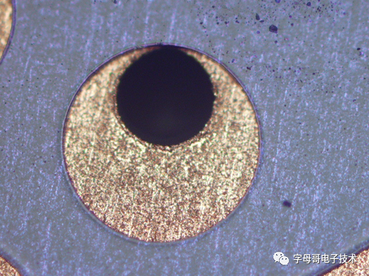 Hole Offset Image
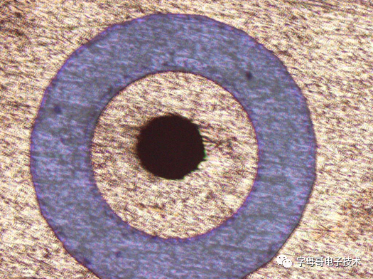 No Hole Offset Image1.2. Potential Causes and Inspection Content① Poor quality of drill bit sharpening, such as uneven edges, leading to inaccurate positioning during drilling.② Excessive drilling drop speed.③ Excessive number of stacked boards.④ Excessive spindle wobble of the drilling machine.⑤ Debris on the board surface.⑥ Unevenness of the backing board and aluminum sheet.⑦ Loose positioning pins.⑧ Positioning pins too high, causing them to be knocked out of alignment during drilling.⑨ Positioning pins too low, causing the board to jump out of position during drilling.⑩ Improper operation when placing the board (especially for thin boards).1.3. Improvement Methods① Control the quality of drill bit sharpening.② Appropriately reduce the drop speed.③ Reduce the number of stacked boards.④ Recalibrate the precision of the drilling machine.⑤ Standardize operations and remove debris from the board surface before drilling.⑥ Replace the backing board with a flat one and sand down any uneven areas on the aluminum sheet.⑦ Check that the size of the positioning pins matches the positioning holes.⑧ Control the height of the positioning pins to be 0.5-1.5mm above the board surface.⑨ When placing thin boards, hold the board with both hands and place it parallel.2. Breakout Holes2.1 Defect Images
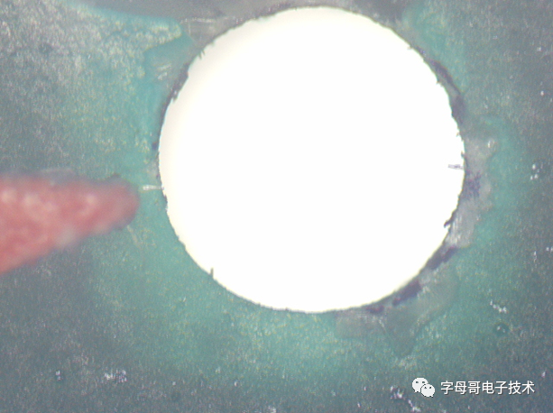 Breakout holes appear white and oily at the edges.2.2. Potential Causes and Inspection Content The board surface is uneven after etching, and there is a gap between the board and the board after placement, causing the back of the board to be suspended during drilling, leading to breakout holes. There are mainly five aspects:① Re-drilling of larger hole diameters:For holes larger than 5mm, breakout holes may occur due to the greater resistance encountered by the drill bit during drilling.② Material reasons: environmentally friendly materials, CEM-3 materials, high Tg materials,These materials are more brittle and prone to breakout holes.③ Excessive lifespan of drill bits leading to wear.④ Excessive drilling drop speed.⑤ Repeated use of the base board.2.3. Improvement Methods① Use step drilling: generally, first use a drill bit that is 0.5mm smaller than the corresponding diameter for pre-drilling, then use the required drill bit for MI.② Reduce drilling drop speed and use low-wear drill bits.③ Reduce the lifespan of drill bits.④ Set drilling drop speed according to MEI requirements.⑤ For larger re-drilled holes, such as those over 5mm, after drilling one board, the backing board should be appropriately moved to prevent overlapping holes on the backing board.3. Short Slot Holes and Skewed Holes3.1 Definition and Classification of Slot Holes:(1) A slot hole with a length-to-width ratio ≤ 2 is called a short slot hole.(2) A slot hole with a length-to-width ratio > 2 is called a long slot hole. The schematic diagram is as follows:
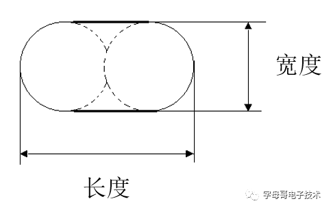
3.2. Potential Causes and Inspection Content
① Uneven force on one side of the drill bit during drilling (the round holes at both ends of the slot become intersecting holes).
② Excessive number of stacked boards and high drilling drop speed settings.
③ Using the wrong drill bit, using a regular drill bit instead of a slot drill bit.
3.3. Improvement Methods① Compensate for the length and angle of slot holes during design.② Reduce the number of stacked boards and lower the drop speed.③ Use the appropriate slot drill bit according to the drilling parameter table.4. Hole Roughness4.1. Types of Hole Roughness:① Fibers inside the hole1>. Defect Images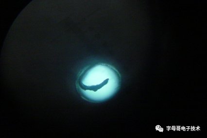 Fiber Image (Flat)2>. Potential Causes and Inspection Content① Low rotation speed.② Wear of the drill bit cutting edge.3>. Improvement Methods① Increase rotation speed.② Strictly control the lifespan of drill bits within the MEI range, or lower than MEI.② Hole Wall Roughness1>. Defect Images Images of rough hole walls and normal hole walls are shown below (cross-section):
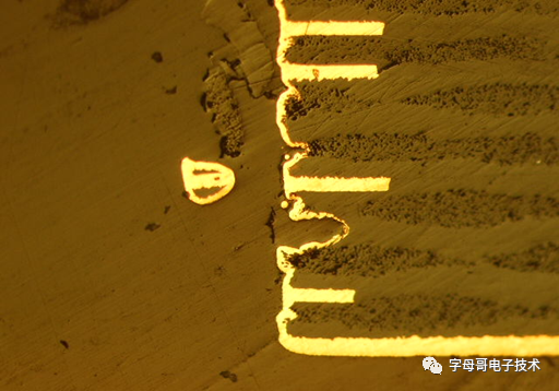
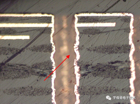 Rough Hole Wall (Uneven)
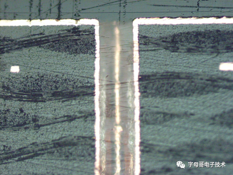 Normal Hole Wall (Smooth and Straight)③ Independent PADs in the inner layer pulling out the hole wall (not connected to the inner layer circuit, which is an independent inner layer copper PAD, non-functional).)
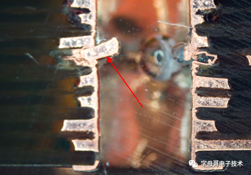
 Independent PAD pulling out the hole wall (cross-section)2>.Potential causes of rough hole walls and independent PADs pulling out the hole wall, i.e., inspection content① Excessive drilling drop speed or excessive number of stacked boards.② Wear or chipping of the drill bit.③ Thick copper in the inner and outer layers.④ Poor dust collection by the vacuum cleaner.⑤ Small independent PADs in the inner layer.3>. Improvement Methods ① Reduce drilling drop speed.② Strictly control the number of stacked boards. For boards with inner and outer copper thickness over 2OZ,the number of stacked boards should be reduced by 1 PNL compared to normal.③ Reduce the lifespan of drill bits to decrease wear. ④ For boards with inner and outer copper thickness ≥ 2OZ:A. Use step drilling: change from single-step drilling to two or three-step drilling.B. After drilling, sand the board surface to remove burrs at the hole entrance.C. After drilling, micro-etch to remove rough copper shavings from the hole wall. ⑤ Ensure the vacuum cleaner is functioning properly, allowing dust generated during drilling to be promptly removed from the hole.⑥ Increase the size of independent PADs or control the quality of inner layer offset and positioning distance anomalies.

Some Screenshots from Electronic Books
【Complete Set of Hardware Learning Materials Collection】