A design is needed for an isolated circuit that outputs a variable voltage of 0~12V, with the isolated side powered by 12V. There are no specific speed requirements for the output voltage. The accuracy is not particularly critical, as it just needs to stabilize once set. The design uses an optocoupler driven by the PWM of an MCU, with a pull-up on the output side connected to a second-order RC low-pass filter using an operational amplifier for buffering. The cutoff frequency of the single-stage low-pass filter is 20Hz. Due to the speed limitations of the optocoupler, the PWM frequency cannot be too high.
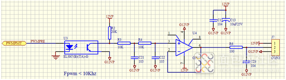
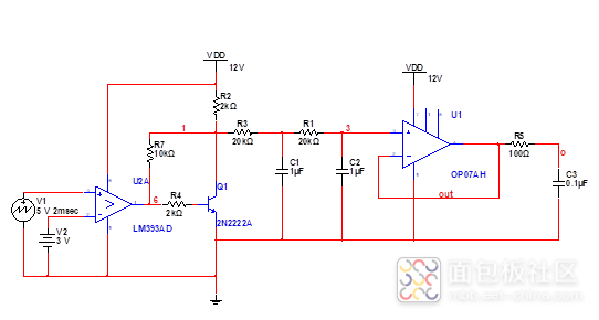
During actual measurements, it was found that the output does not have a proportional relationship with the input. Changing the PWM duty cycle from 0 to 100% resulted in an output of 6V to 1.5V, rather than the theoretical 12V~0V. The inability to reach 0V is related to the input-output range of the operational amplifier; according to the manual, the typical output value is ±2V from the voltage rail. It can only reach 6V, which is related to the pull-up resistor. The filter’s input charges slowly and discharges quickly. To achieve consistent charge and discharge rates, the value of R2 (the pull-up resistor) needs to be reduced. Considering resistor power consumption, a reasonable value for a 0603 resistor at 12V is 2KΩ. However, this results in poor linearity between output and duty cycle. After changing the resistors R3 and R4 that make up the filter to 20K, the linearity improved somewhat. A triangle wave generator and a comparator were used to create a voltage-controlled duty cycle variation driver, simulating the output Vout with a voltage scan from 0 to 5V to analyze the transient response of the circuit.
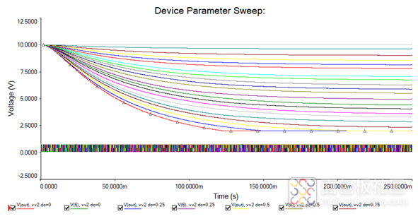
It can be observed that when the duty cycle is below 10%, the output is 2V, and when the duty cycle is above 90%, the output is 10V, with other duty cycles varying linearly.
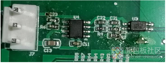
After modifying the circuit, the actual test showed that the voltage output range is 1.5~10.5V within the variable range, and the duty cycle has a linear relationship with the output voltage in the range of 10%~90%. Using this method to create an isolated DAC requires consideration of two issues:
1. The output voltage range of the operational amplifier used for output. In fact, the input voltage range should also be considered.
2. The output impedance of the PWM signal source involved in generating the signal will affect linearity.
Author: Breadboard Community Blogger southcreek