RS-232, RS-422, and RS-485 all belong to UART, which stands for Universal Asynchronous Receiver/Transmitter. They can complete the communication process using only two signal lines (Rx and Tx);
It should be noted that: RS-232, RS-422, and RS-485 are merely mechanical and electrical interface standards regarding UART communication. Therefore, it is incorrect to refer to RS-232, RS-422, and RS-485 as communication protocols (at most, they are related to the physical layer of network protocols).
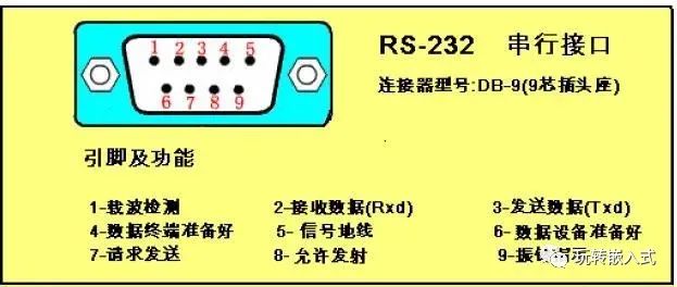
RS-232 generally only uses three lines: RXD (2), TXD (3), and GND (5);
Hardware Principles
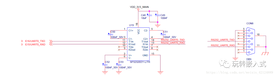
First, the change of voltage levels is involved, where the chip used by UART outputs its own voltage;
Then, the two signal lines of UART, TX and RX, are converted to the TX and RX of RS-232;
The signal voltage levels of the RS-232 interface are relatively high, which can damage the interface circuit chips. Additionally, since it is not compatible with TTL levels, a level conversion circuit is required to connect with TTL circuits.
It has a low transmission rate, with a baud rate of 20Kbps during asynchronous transmission.
The interface uses one signal line and one signal return line to form a common-ground transmission method. This common-ground transmission is prone to common-mode interference, resulting in weak noise resistance.
The RS-232 interface can achieve point-to-point communication but cannot support networking.
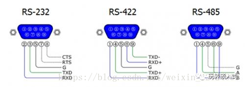
The electrical performance of RS-422 is identical to that of RS-485.
The main difference is: RS-422 has four signal lines: two for sending and two for receiving. Since RS-422 separates send and receive, it can transmit and receive simultaneously (full duplex). Because full duplex requires separate channels for sending and receiving, RS-422 is suitable for communication between two stations, star networks, and ring networks, but not for bus networks;
RS-485 has only two signal lines, so it can only operate in half-duplex mode and is commonly used in bus networks.
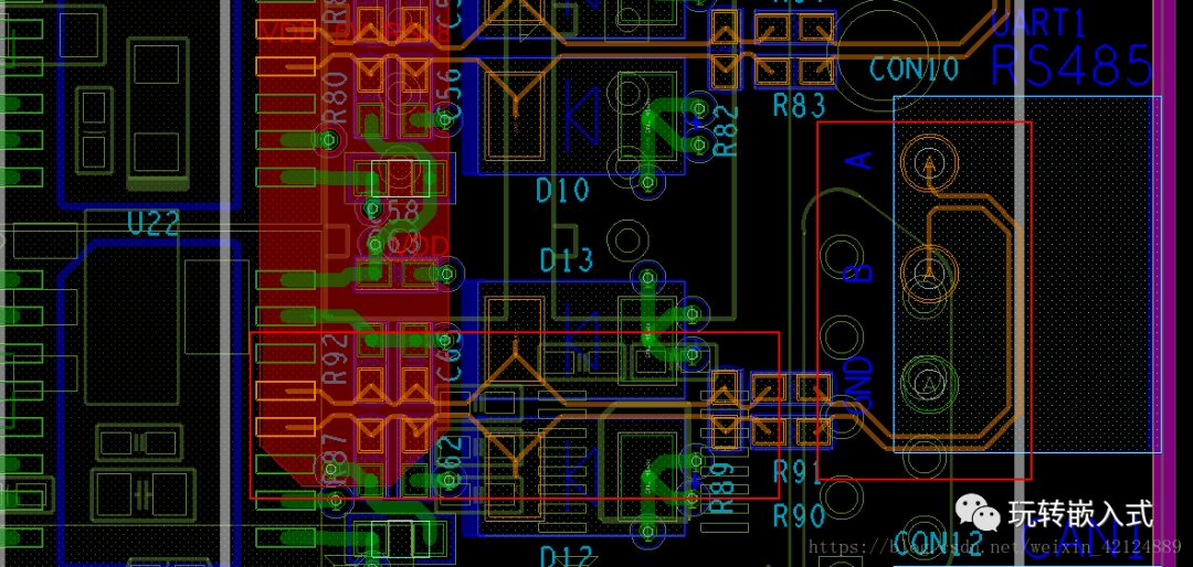
Hardware Principles
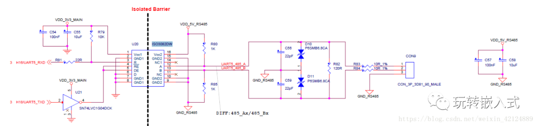
Note that the two signal lines of RS-485 need to be of equal length for differential signaling.
1. Communication Capability: The RS-485 interface allows for the connection of up to 128 transceivers on a bus, enabling users to easily establish a device network using a single RS-485 interface. RS-232 only allows point-to-point communication.
RS-422 can support 10 nodes, while RS-485 supports 32 nodes, thus forming a multi-node network.
The network topology generally adopts a terminal-matched bus structure and does not support ring or star networks.
2. Signal Lines: A half-duplex network composed of RS-485 typically only requires two signal lines. The RS-232 interface generally uses three lines: RXD, TXD, and GND.
3. Electrical Voltage Levels: The logic “1” of RS-485 is represented by a voltage difference of + (2-6) V between the two lines; logic “0” is represented by a voltage difference of – (2-6) V. In RS-232-C, any signal line has a negative logic relationship, meaning: logic “1” is -5 to -15V; logic “0” is +5 to +15V.
4. Transmission Rate: RS-232 has a low transmission rate, with a baud rate of 20Kbps during asynchronous transmission. RS-485 has a maximum data transmission rate of 10Mbps.
5. Transmission Rate: RS-232 has a low transmission rate, with a baud rate of 20Kbps during asynchronous transmission. RS-485 has a maximum data transmission rate of 10Mbps.
6. Interference Resistance: The RS-485 interface uses a combination of balanced drivers and differential receivers, providing good noise resistance. The RS-232 interface uses one signal line and one return line, forming a common-ground transmission method that is prone to common-mode interference.
Reference Original Article:https://blog.csdn.net/weixin_42124889/article/details/80253009